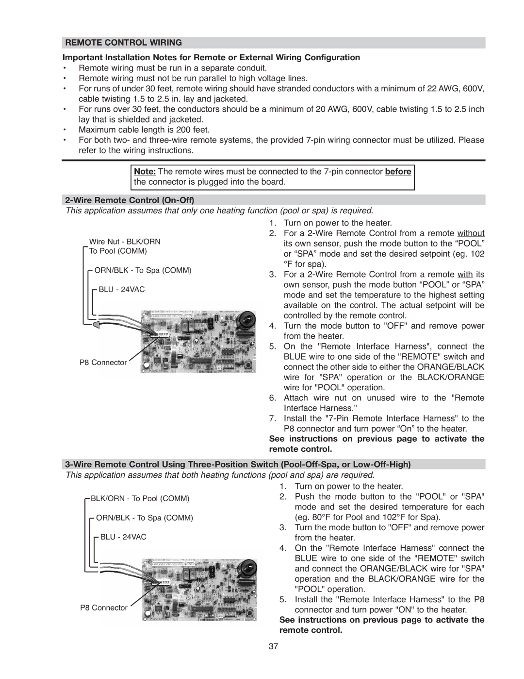
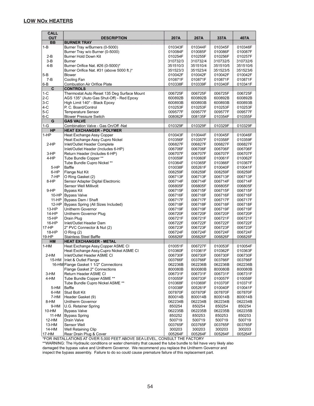
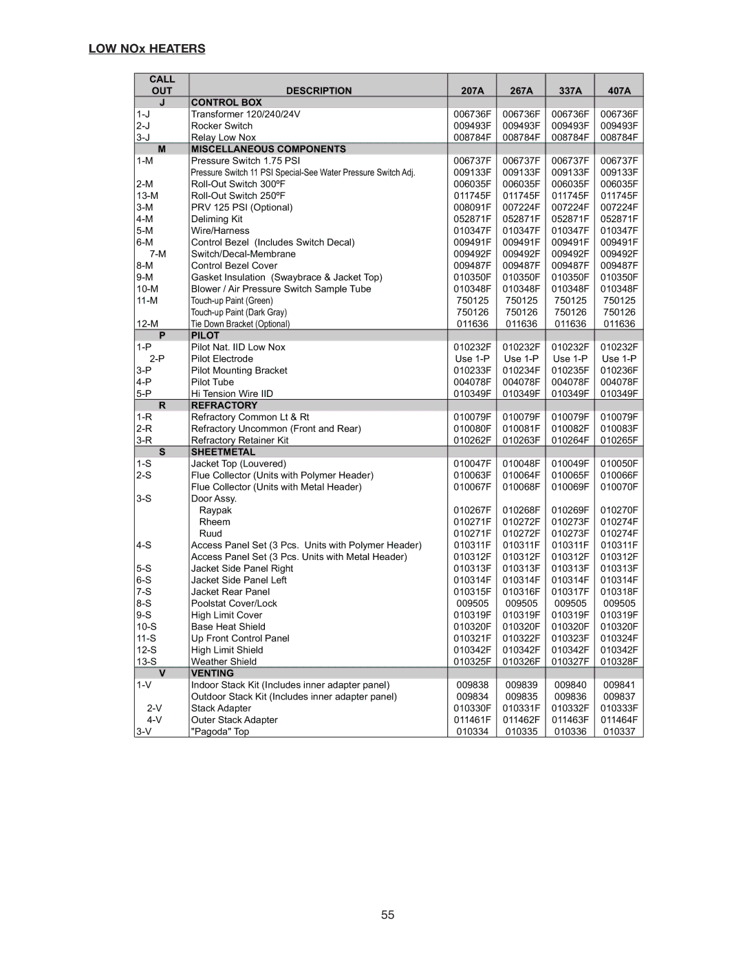

LOW NOx HEATERS (CONTINUED)
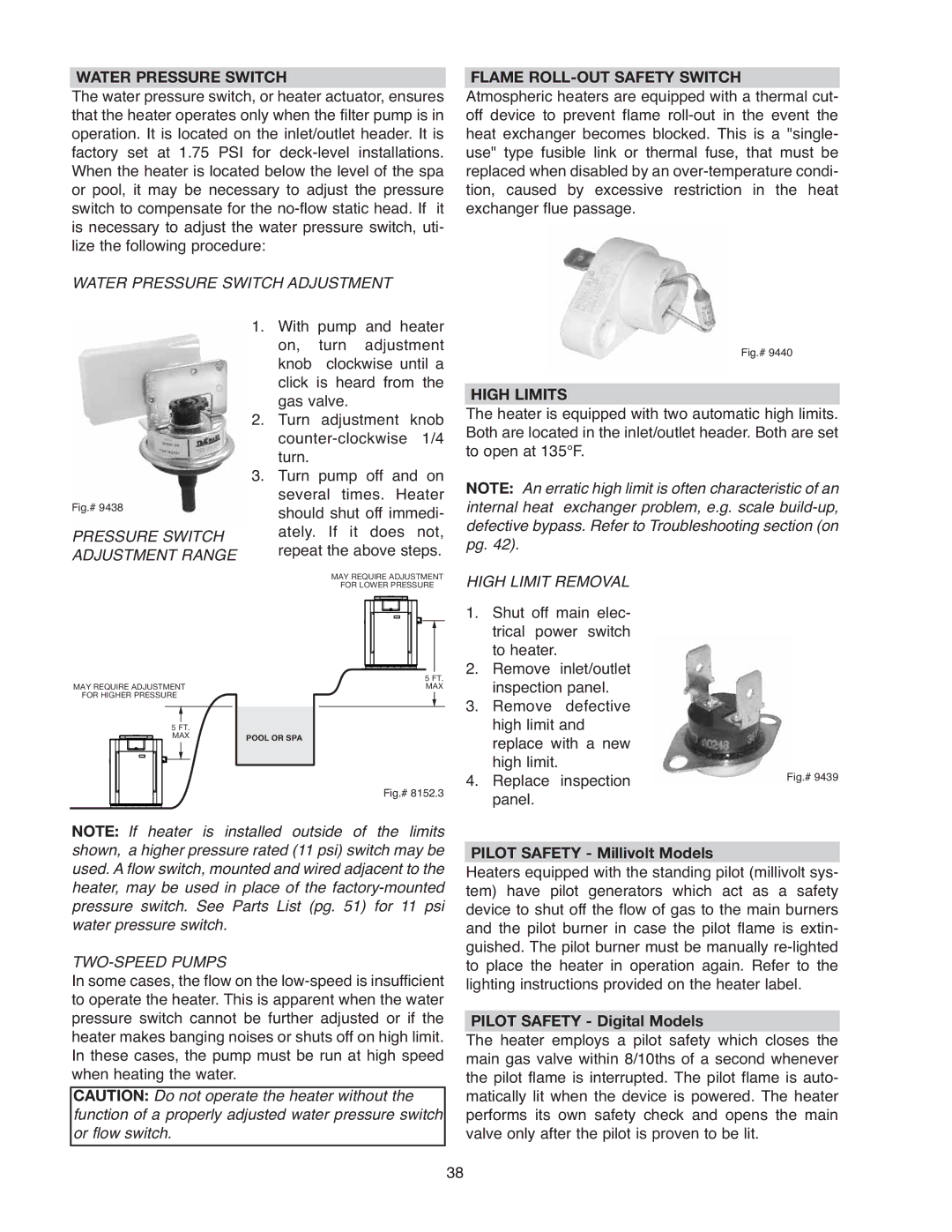
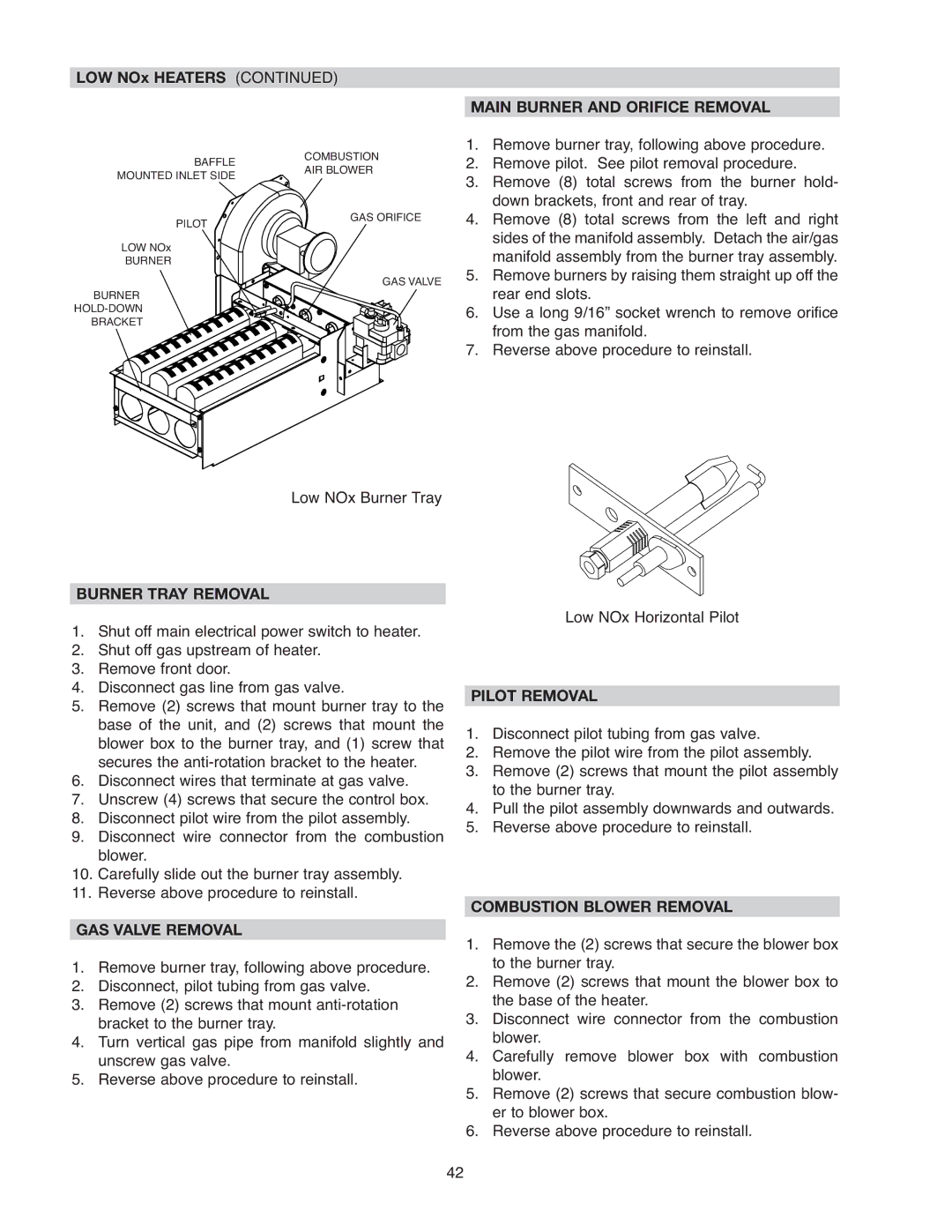
BAFFLE | COMBUSTION | |
AIR BLOWER | ||
MOUNTED INLET SIDE | ||
|
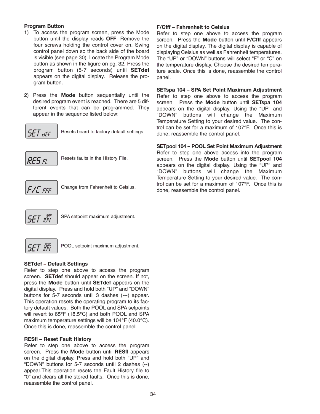
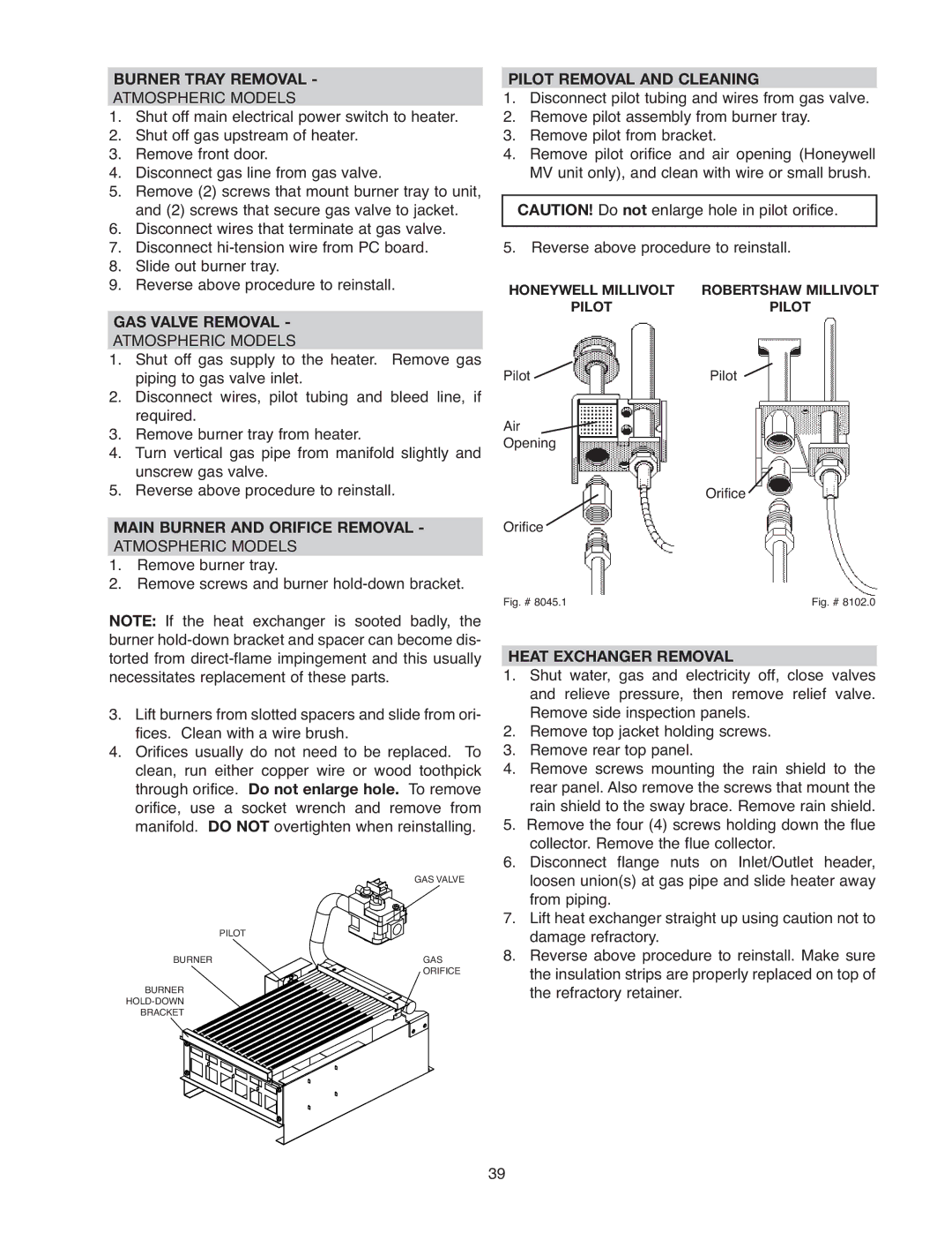
MAIN BURNER AND ORIFICE REMOVAL
1. | Remove burner tray, following above procedure. |
2. | Remove pilot. See pilot removal procedure. |
3. | Remove (8) total screws from the burner hold- |
| down brackets, front and rear of tray. |
PILOT
LOW NOx
BURNER
BURNER
BRACKET
GAS ORIFICE
GAS VALVE
4. | Remove (8) total screws from the left and right |
| sides of the manifold assembly. Detach the air/gas |
| manifold assembly from the burner tray assembly. |
5. | Remove burners by raising them straight up off the |
| rear end slots. |
6. | Use a long 9/16” socket wrench to remove orifice |
| from the gas manifold. |
7. | Reverse above procedure to reinstall. |
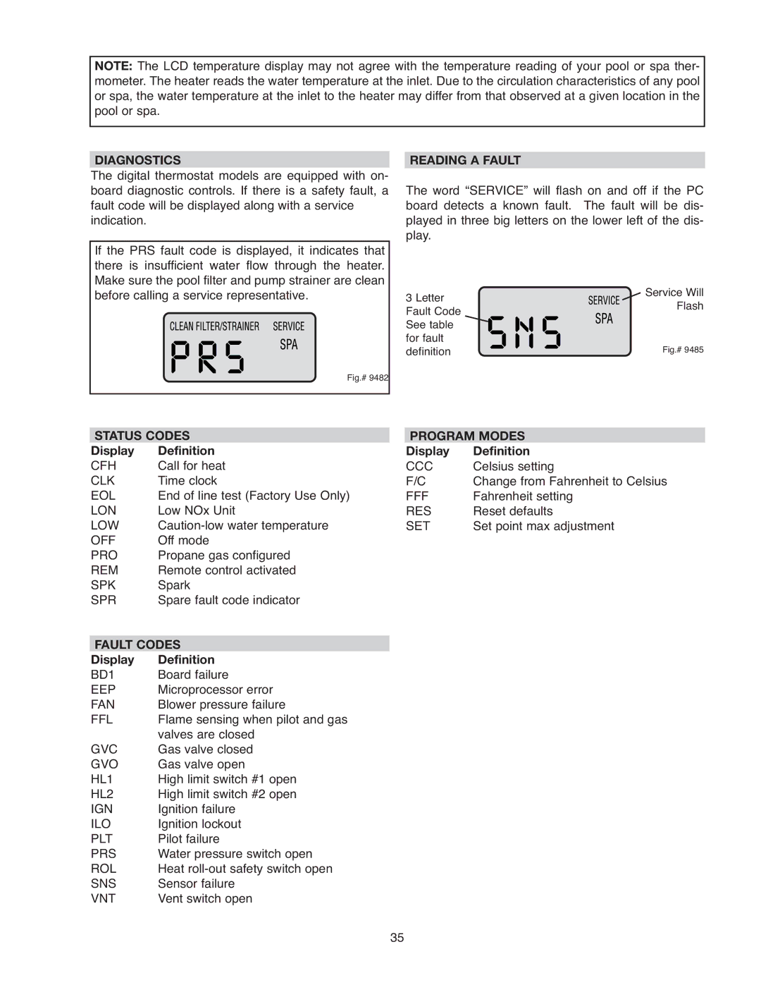
Low NOx Burner Tray
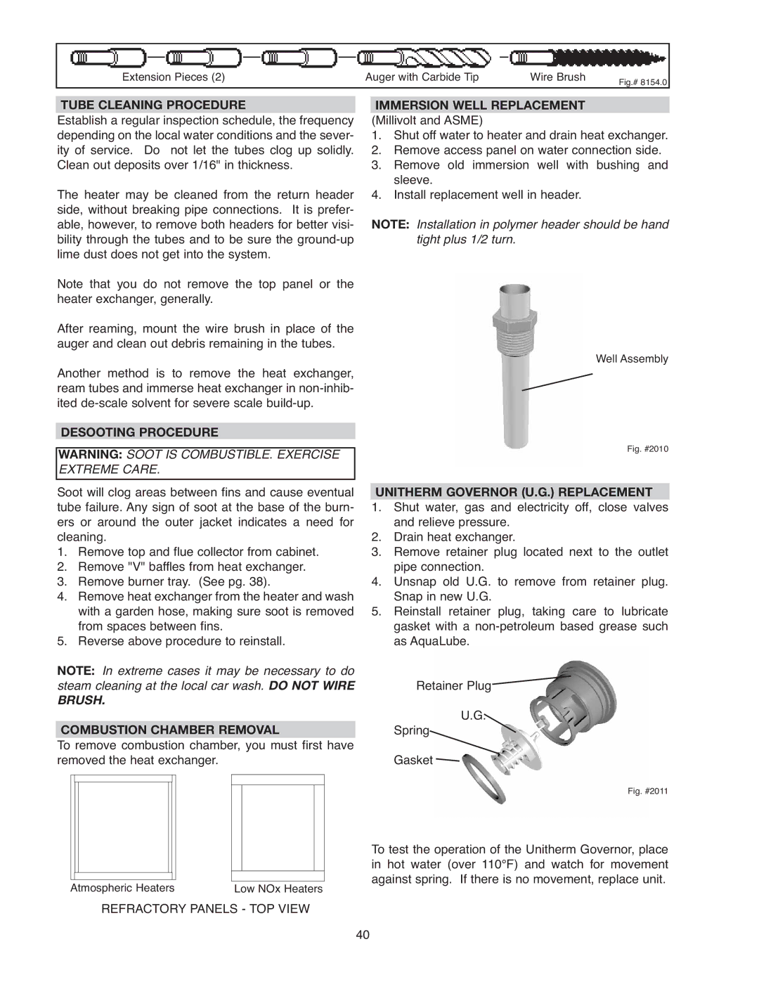
BURNER TRAY REMOVAL
1.Shut off main electrical power switch to heater.
2.Shut off gas upstream of heater.
3.Remove front door.
4.Disconnect gas line from gas valve.
5.Remove (2) screws that mount burner tray to the base of the unit, and (2) screws that mount the blower box to the burner tray, and (1) screw that secures the
6.Disconnect wires that terminate at gas valve.
7.Unscrew (4) screws that secure the control box.
8.Disconnect pilot wire from the pilot assembly.
9.Disconnect wire connector from the combustion blower.
10.Carefully slide out the burner tray assembly.
11.Reverse above procedure to reinstall.
GAS VALVE REMOVAL
1.Remove burner tray, following above procedure.
2.Disconnect, pilot tubing from gas valve.
3.Remove (2) screws that mount
4.Turn vertical gas pipe from manifold slightly and unscrew gas valve.
5.Reverse above procedure to reinstall.
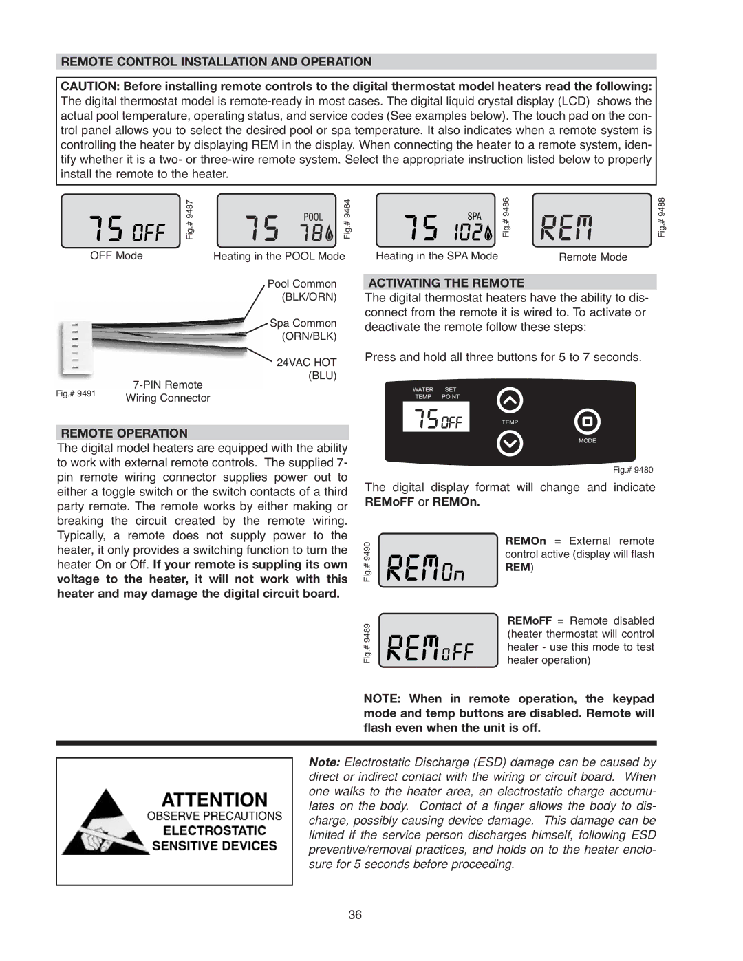
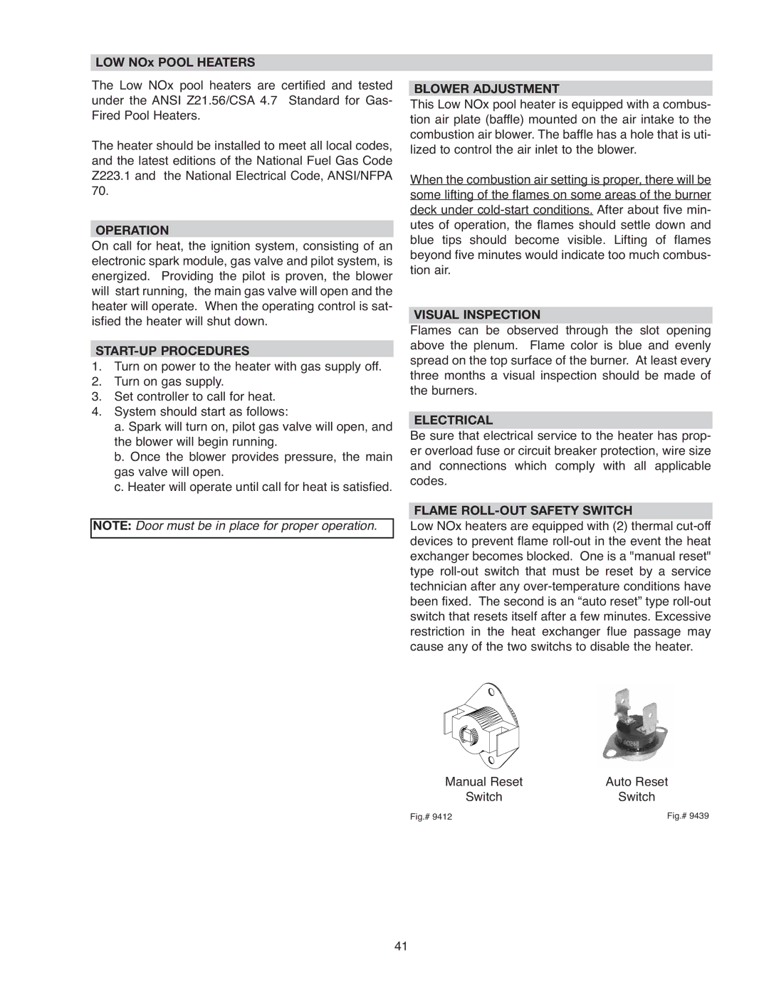
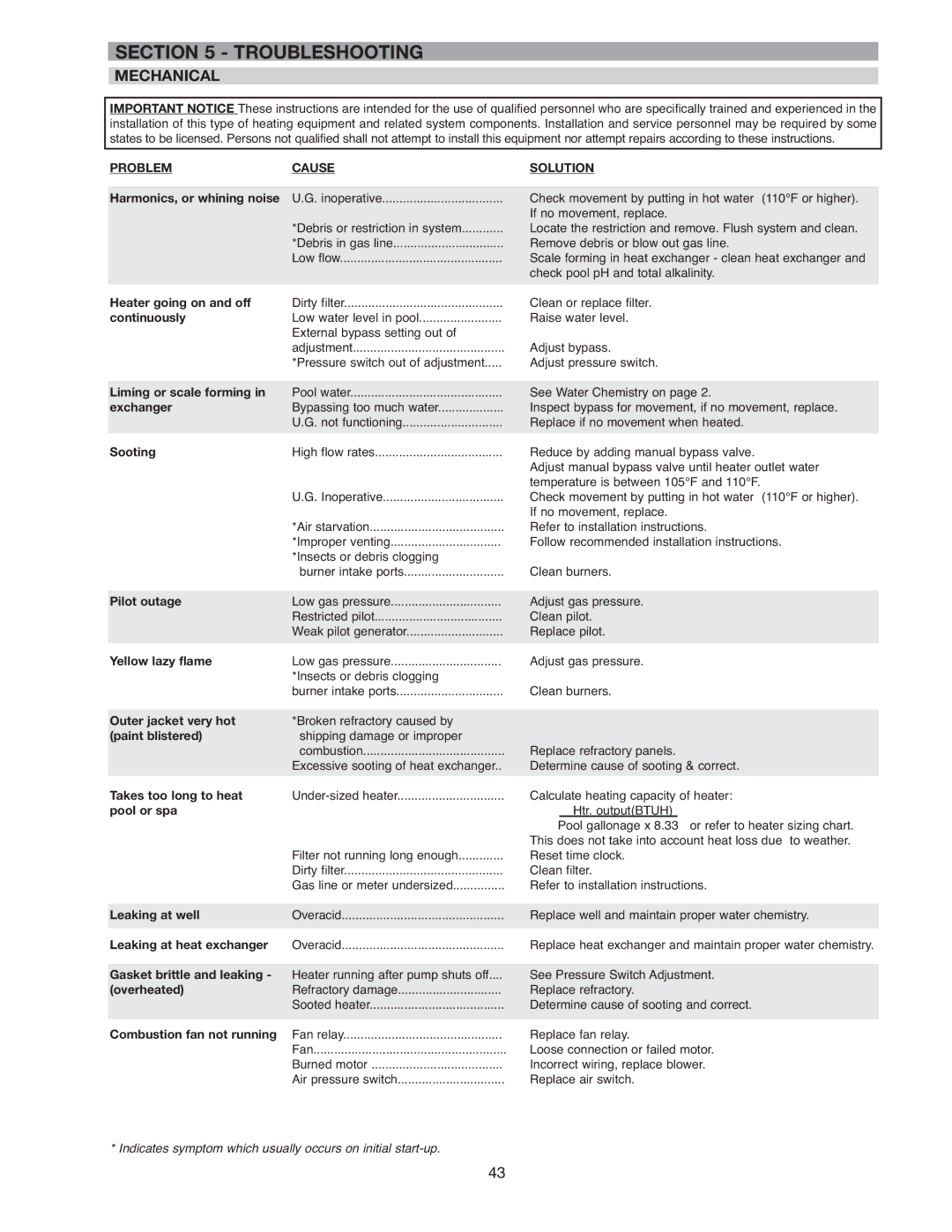
Low NOx Horizontal Pilot
PILOT REMOVAL
1.Disconnect pilot tubing from gas valve.
2.Remove the pilot wire from the pilot assembly.
3.Remove (2) screws that mount the pilot assembly to the burner tray.
4.Pull the pilot assembly downwards and outwards.
5.Reverse above procedure to reinstall.
COMBUSTION BLOWER REMOVAL
1.Remove the (2) screws that secure the blower box to the burner tray.
2.Remove (2) screws that mount the blower box to the base of the heater.
3.Disconnect wire connector from the combustion blower.
4.Carefully remove blower box with combustion blower.
5.Remove (2) screws that secure combustion blow- er to blower box.
6.Reverse above procedure to reinstall.
42