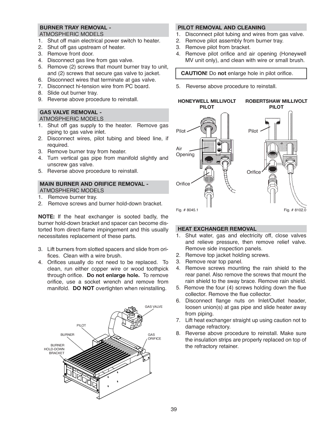
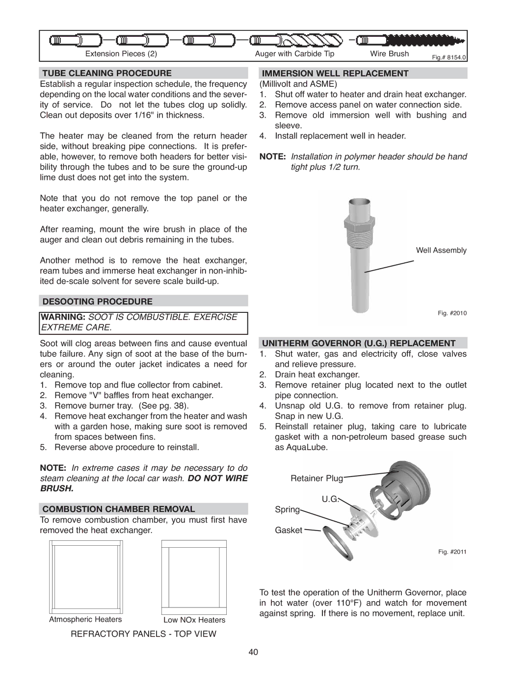
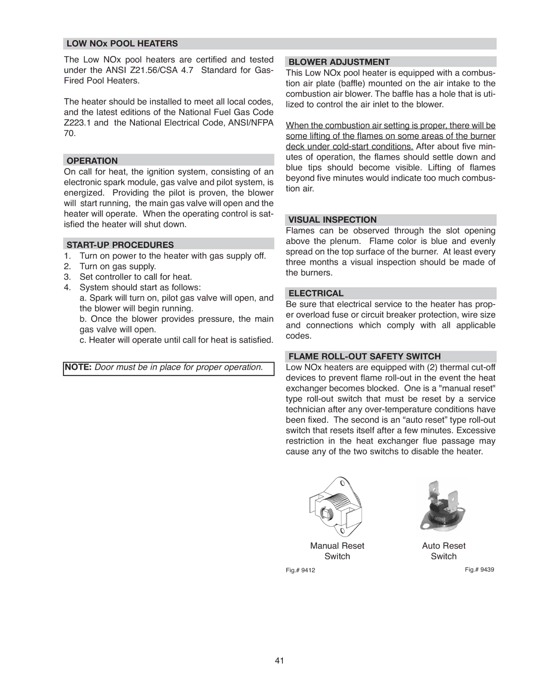
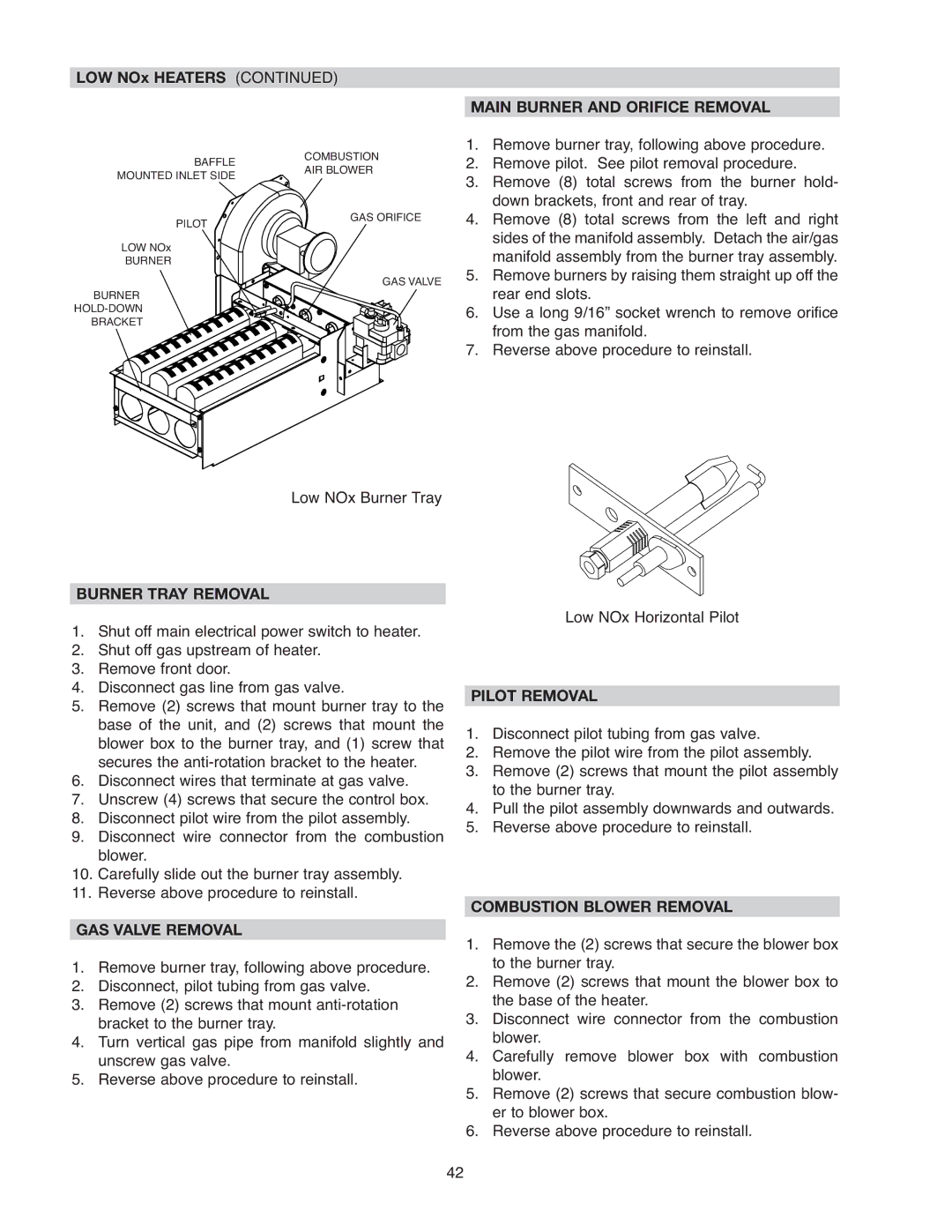
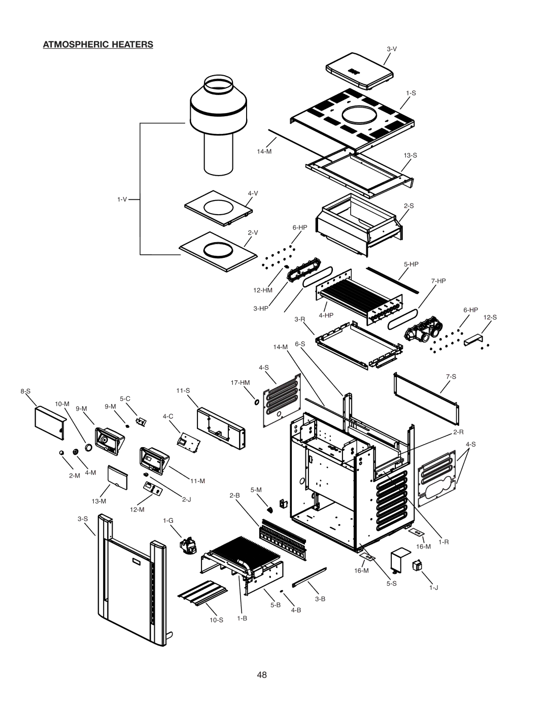
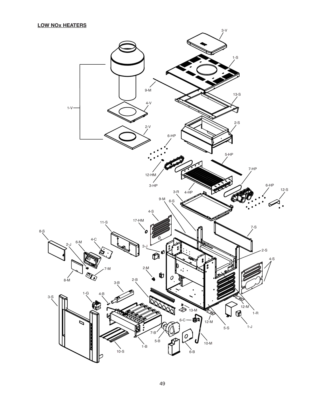
Raypak 337A, 406A Diagnostics Reading a Fault, Status Codes Program Modes, Display Definition

Page 35

NOTE: The LCD temperature display may not agree with the temperature reading of your pool or spa ther- mometer. The heater reads the water temperature at the inlet. Due to the circulation characteristics of any pool or spa, the water temperature at the inlet to the heater may differ from that observed at a given location in the pool or spa.

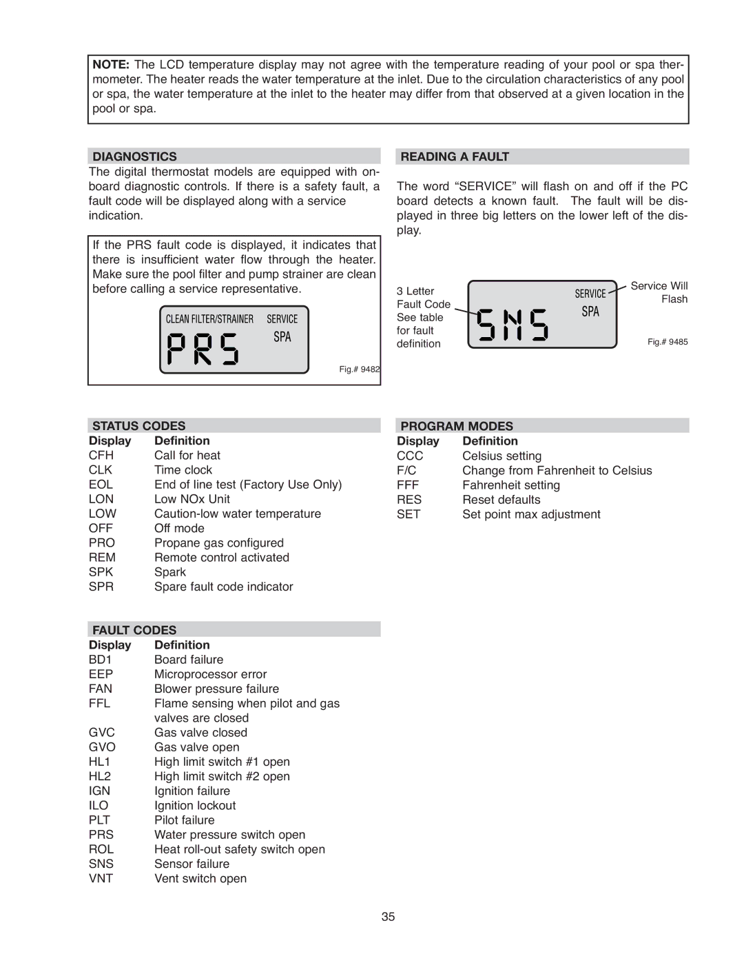
DIAGNOSTICS


READING A FAULT

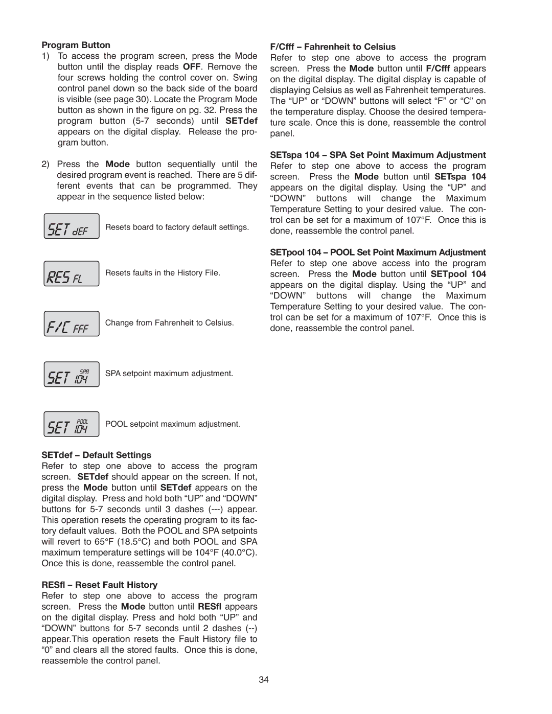
The digital thermostat models are equipped with on- board diagnostic controls. If there is a safety fault, a fault code will be displayed along with a service indication.

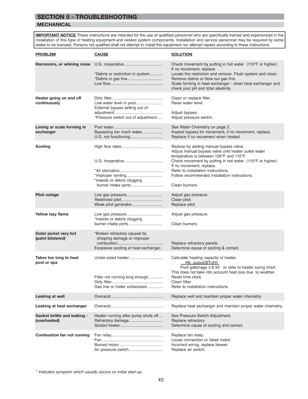
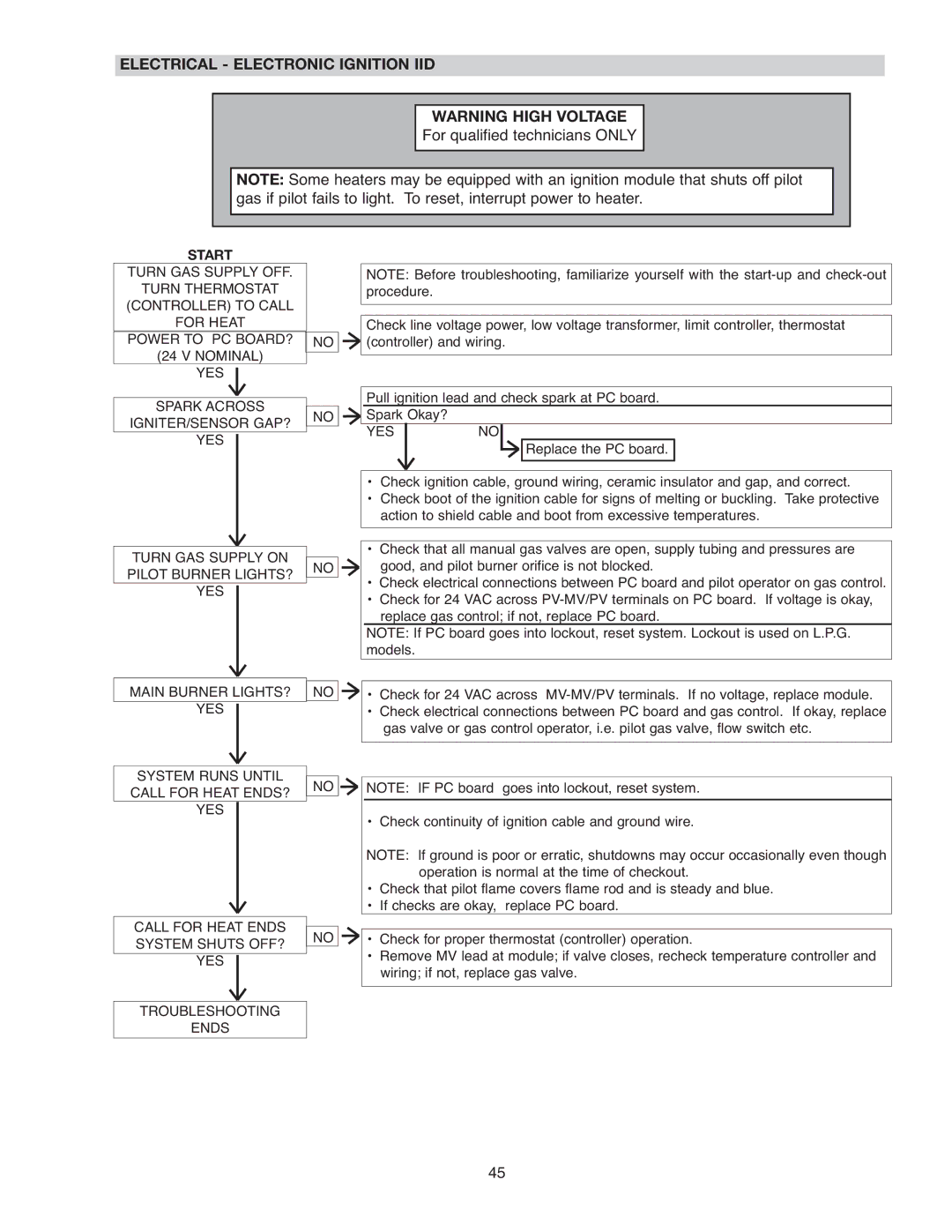
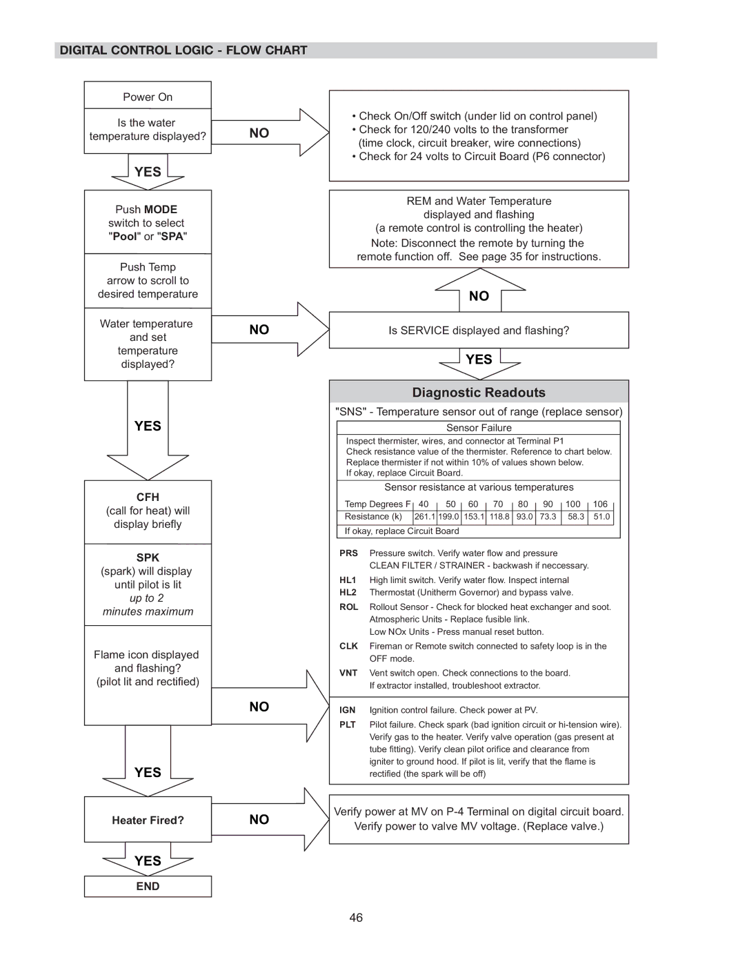
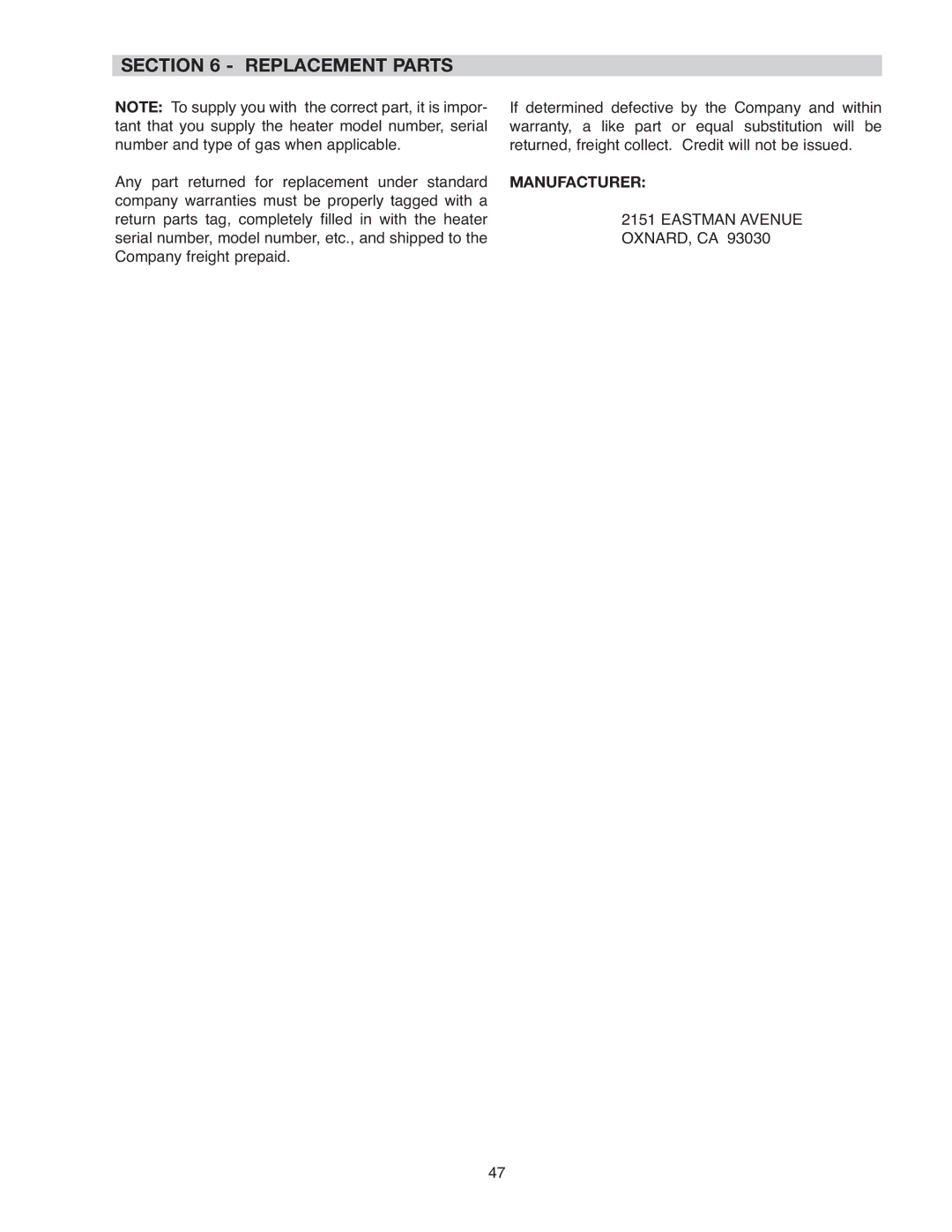
If the PRS fault code is displayed, it indicates that there is insufficient water flow through the heater. Make sure the pool filter and pump strainer are clean before calling a service representative.

The word “SERVICE” will flash on and off if the PC board detects a known fault. The fault will be dis- played in three big letters on the lower left of the dis- play.

3 Letter


Service Will


Flash

Fault Code


See table


for fault


definition

Fig.# 9485

Fig.# 9482

STATUS CODES


PROGRAM MODES

Display

Definition


Display

Definition

CFH

Call for heat

CCC

Celsius setting

CLK

Time clock

F/C

Change from Fahrenheit to Celsius

EOL

End of line test (Factory Use Only)

FFF

Fahrenheit setting

LON

Low NOx Unit

RES

Reset defaults

LOW

Caution-low water temperature

SET

Set point max adjustment

OFF

Off mode


PRO

Propane gas configured


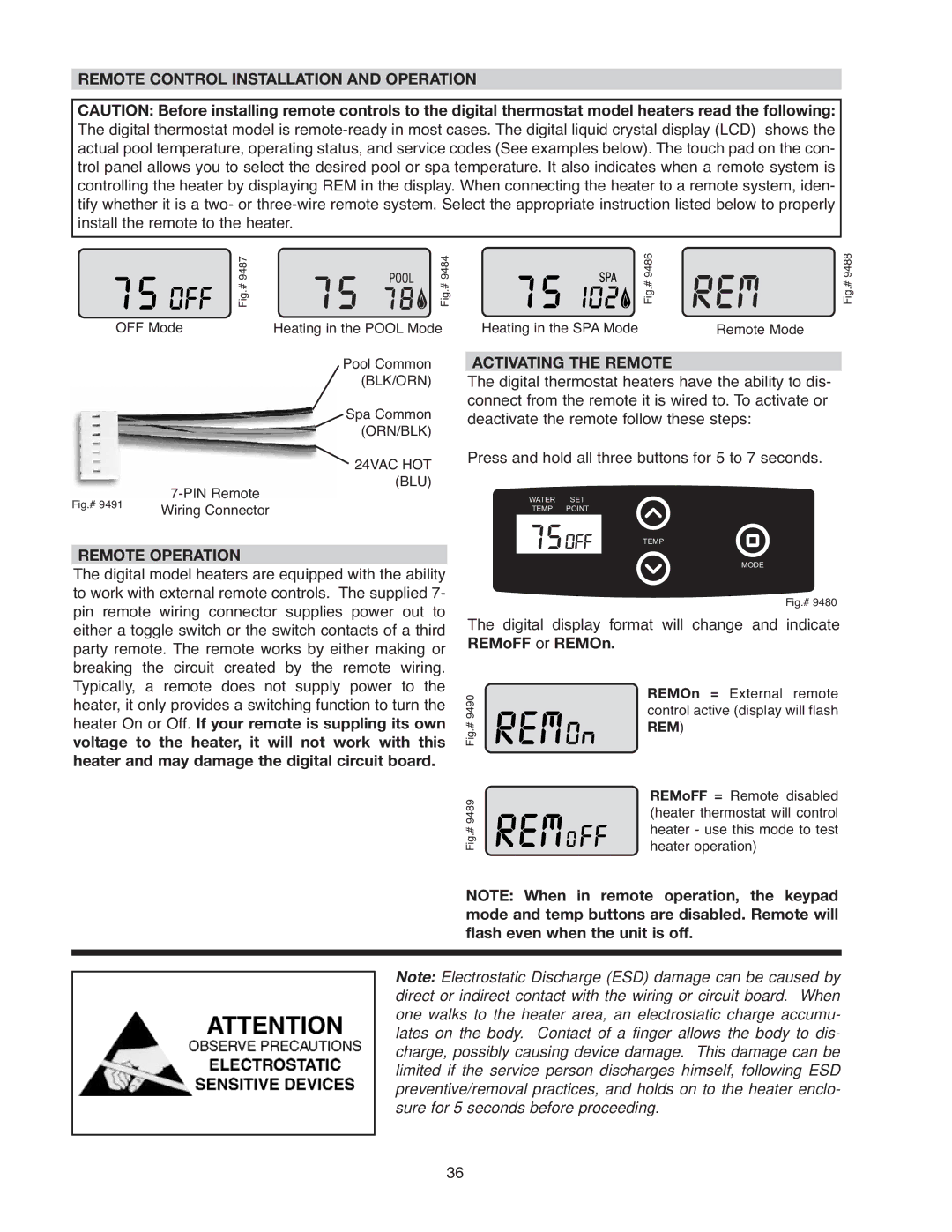
REM

Remote control activated


SPK

Spark


SPR

Spare fault code indicator


FAULT CODES


Display

Definition


BD1

Board failure


EEP

Microprocessor error


FAN

Blower pressure failure


FFL

Flame sensing when pilot and gas


valves are closed


GVC

Gas valve closed


GVO

Gas valve open


HL1

High limit switch #1 open


HL2

High limit switch #2 open


IGN

Ignition failure


ILO

Ignition lockout


PLT

Pilot failure


PRS

Water pressure switch open


ROL

Heat roll-out safety switch open


SNS

Sensor failure


VNT

Vent switch open


35

Image 35
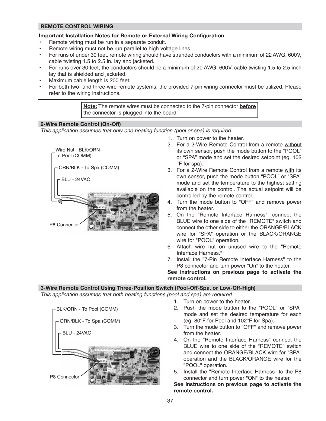
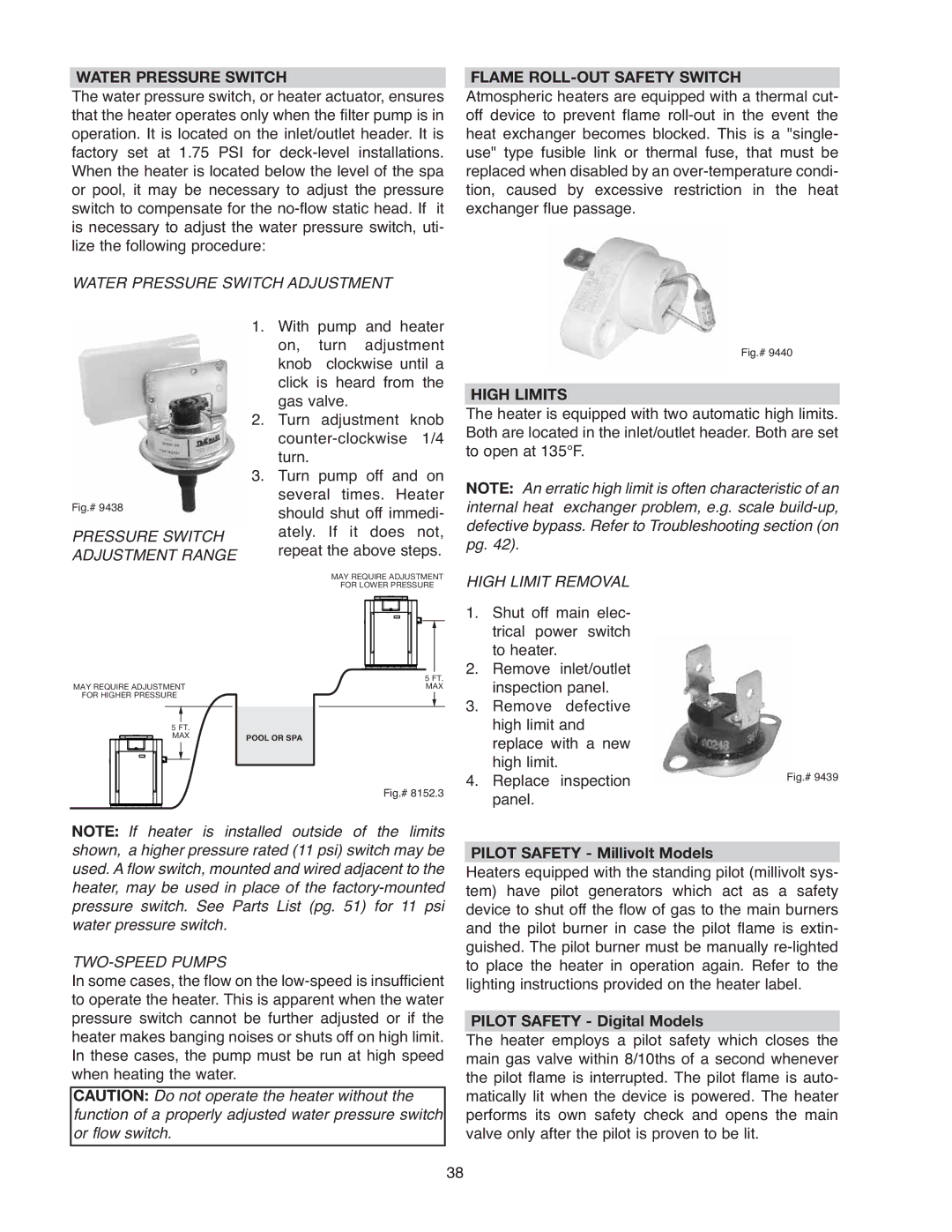
Contents What to do if YOU Smell GAS Installation and Operating InstructionsMaximum Water ChemistryContents Before START-UP Burners Water START-UP ProceduresFor Your Safety Read Before Operating Millivolt System Automatically Lighted Pilot Operating Instructions and SHUT-OFF ProceduresSHUT-OFF Procedures Electronic Ignition SystemVisual Inspection Atmospheric Heaters Water Pressure SwitchAfter START-UP Pool & SPA Water Chemistry Maintenance and Care ProceduresSee plumbing diagram If Heater will not FireWinterizing the Pool & SPA Heater Important Freeze InformationCold Weather Operation Receiving Equipment Part TWO Installation and Service InstructionsCode Requirements General SpecificationsInstallation Instructions Important NoticeALL Heaters Outdoor InstallationOutdoor Heater Installation Clearances10 ft Wind Speed = 150 MPH, 3 Second Gust Exposure = C Florida Building CodeOutdoor Stack Indoor Stack Indoor Heater InstallationAtmospheric Units Specifications and DimensionsLow NOx Units Vent Piping Power Vent Kit Model Part NoCombustion and Ventilation AIR Indoor Units Only Model Square InchesGAS Supply Connections B149.1 and B149.2Pipe Sizing for GAS Connections GAS Pressure Adjustment LocationsGAS Pressure Regulator Polymer Headers Cast Iron Headers Asme Plumbing for Water ConnectionsFlow Rates Unitherm Governor Operation INLET/OUTLET Header PolymerCast Iron Headers Asme Models INLET/OUTLET Header AsmeExternal Auxiliary Bypass Valve Auxiliary Bypass Valve AdjustmentCast Iron Header Asme Models Fig. #4 Heat Exchanger Reversal Procedure Standard ModelsAtmospheric Electrical WiringMillivolt Models Digital Models240V Atmospheric Heater Transformer Wiring VAC Wiring120V Atmospheric Heater Wiring Diagram Millivolt Mechanical Thermostat Wiring Diagram Digital Models Atmospheric Wiring Diagram Digital Models LOW NOx LOW NOx Servicing InstructionsGeneral Location of Controls Atmospheric Control Panel Removal Control Adjustments Digital ModelsControl Adjustments Millivolt Models Thermostat Control Operation Digital Thermostat ControlsCfff Fahrenheit to Celsius SETdef Default SettingsRESfl Reset Fault History Program ButtonDisplay Definition Diagnostics Reading a FaultFault Codes Status Codes Program ModesActivating the Remote Remote Control Installation and OperationRemote Operation Wire Remote Control On-Off Remote Control WiringHigh Limits Flame ROLL-OUT Safety SwitchPilot Safety Millivolt Models Pilot Safety Digital ModelsMain Burner and Orifice Removal Pilot Removal and CleaningBurner Tray Removal GAS Valve RemovalUnitherm Governor U.G. Replacement Tube Cleaning ProcedureDesooting Procedure Immersion Well ReplacementVisual Inspection Blower AdjustmentLOW NOx Pool Heaters OperationCombustion Blower Removal Pilot RemovalMechanical TroubleshootingPage For qualified technicians only Electrical Electronic Ignition IIDYES Digital Control Logic Flow ChartEastman Avenue OXNARD, CA Replacement PartsManufacturer Atmospheric Heaters LOW NOx Heaters IID LOW NOx Pilot Call OUT Description Call OUT Description Sheetmetal Call OUT Description 267A