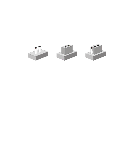
Intel SBC-780 manual Setting Jumpers, Open Closed

Page 23

F u l l - Size CPU Card

S B C - 7 8 0


2.6 Setting Jumpers

You configure your card to match the needs of your application by setting jumpers. A jumper is the simplest kind of electric switch. It consists of two metal pins and a small metal clip (often protected by a plastic cover) that slides over the pins to connect them. To “close” a jumper you connect the pins with the clip.

To “open” a jumper you remove the clip. Sometimes a jumper will have three pins, labeled 1, 2 and 3. In this case you would connect either pins 1 and 2 or 2 and 3.

1 2 3

Open

Closed

Closed 2-3

A pair of needle-nose pliers may be helpful when working with jumpers.

If you have any doubt about the best hardware configuration for your application, contact your local distributor or sales representative before you make any change.

Generally, you simply need a standard cable to make most connections.

Chapter 2 Quick Installation Guide

2 - 10

Image 23
Contents SBC-780 Copyright Notice Acknowledgments Packing List Contents Award Bios Setup Driver Installation General Information Introduction Features System SpecificationsUSB Display Quick Installation Guide Safety Precautions I P S Locating connector solder side Mechanical Drawing Mechanical drawing component side Mechanical Drawing solder side List of Jumpers JumpersList of Connectors ConnectorsDIMM1 Open Closed Setting JumpersCOM2 RS-232/422/485 Selection JP6&JP7 LCD Voltage Selection JP2Tftlcd Clock Selection JP3 12 COM2 Ring/+5V/+12V Selection JP11 Clear Cmos JP8PCI-104 I/O Voltage Selection JP10 Ttllcd Connector CN2 Optional ATX Power Connector CN1Ttllcd Connector CN3 Channel 2 Lvds Connector CN5 Channel 1 Lvds Connector CN4USB Connectors CN8/CN9 USB1 Connector CN8USB2 Connector CN9 SIR Connector CN621 COM2 RS-232/422/485 Serial Port ConnectorCN11 LPT Port ConnectorCN10Floppy ConnectorCN12 Power Connector CN14 / CN15 23 COM1 RS-232 Serial Port Connector CN1325 PS2 Keyboard/Mouse Connector CN17 VGA Display Connector CN18 CompactFlashä Disk Connector CN21 Audio Input/Output Connector CN24 Internal Keyboard Connector CN22Internal Mouse Connector CN23 Primary/Secondary Hard Drive Connector IDE1&IDE2 Pin Signal Fan Connectors FAN1&FAN2IDE LED IDE LED+ Front Panel Connector JP5Award Bios Setup System test and initialization  Main Standard Cmos Features  Entering setup Major Setup Features  Advanced Features Setup PC Health Setup  Default Load Optimized Defaults Security Password  Exit Without Saving  Clk/Voltage Setup Save & Exit Setup  Exit Date and Time Configuration  Standard Cmos setupMain Setup  Drive a  Drive B  IDE Primary/Secondary Master/Slave IDE HDD Auto-Detection  IDE Primary/Secondary Master/Slave Base Memory  Video Halt On  Select Display DeviceAdvanced Features Setup  Virus Warning  Quick Power On Self Test First/Second/Third Boot Device  Swap Floppy Drive  Boot Other Device Boot Up Floppy Seek  Boot Up NumLock Status Typematic Rate Chars/Sec  Typematic Rate Setting Typematic Delay Msec  Gate A20 Option OS Select For Dram 64MB  Video Bios Shadow Security Option  Frame Buffer Size  Advanced Chipset features setup Dram Timing By SPD  Memory Hole OnChip USB  Boot Device Select AGP Aperture Size  Panel Type OnChip IDE Channel0 / OnChip IDE Channel1  IDE Prefetch Mode Integrated Peripherals  Onboard LAN1/LAN2  Primary/Secondary Master/Slave PIO Primary/Secondary Master/Slave Udma  Init Display First IR Function Duplex  IDE HDD Block Mode Uart 2 Mode  Onboard Serial Port 1/ Port Onboard Parallel Port  Tx, Rx inverting enable Onboard Parallel Mode  ECP Mode Use DMA SB DMA Select  Sound Blaster SB I/O Base Address  SB IRQ Select Acpi Function  Power Management Setup Power Management  Modem Use IRQ  PM Control by APM Video off Option  Video off Method Soft-Off by Pwrbtn  State After Power FailureThis option will not be availa Ble when AT power is Applied  Date of Month  Resume Time hhmmss  Primay Intr  PCI MasterChoices Enabled, Disabled  Reset Configuration Data  PnP/PCI Configuration PNP OS Installed  DMA Resources PCI/ISA PnP Resources Controlled By  IRQ Resources Assign IRQ For USB  PCI/VGA Palette Snoop Assign IRQ For VGA Default Setup  Load Optimized DefaultsSecurity Setup  Set/Change passwordPC Health Setup  CPU Warning Temperature Shutdown Temperature  Power on show status CPU fan low speed warning  Spread Spectrum 6 Clk/Voltage Setup Auto Detect DIMM/PCI CLK  Exit without saving  Save & Exit SetupExit Setup Driver Installation Applicable for Windows 2000/98/ME/XP Please follow the sequence below to install the driversCd-rom \Driver\ Install VIA 4-in-1 Driver C 7 8 Programming Watchdog Timer Programming ResetCompactFlash Cover Installation Guide Plug in CompactFlash Card How to install the CompactFlash coverC 7 8 Press a little bit with the finger on the hole of the cover Done Pull the cover a little bit from the corner indicated How to disassemble the CompactFlash coverPull the cover hard from the reverse corner indicated