


Setting
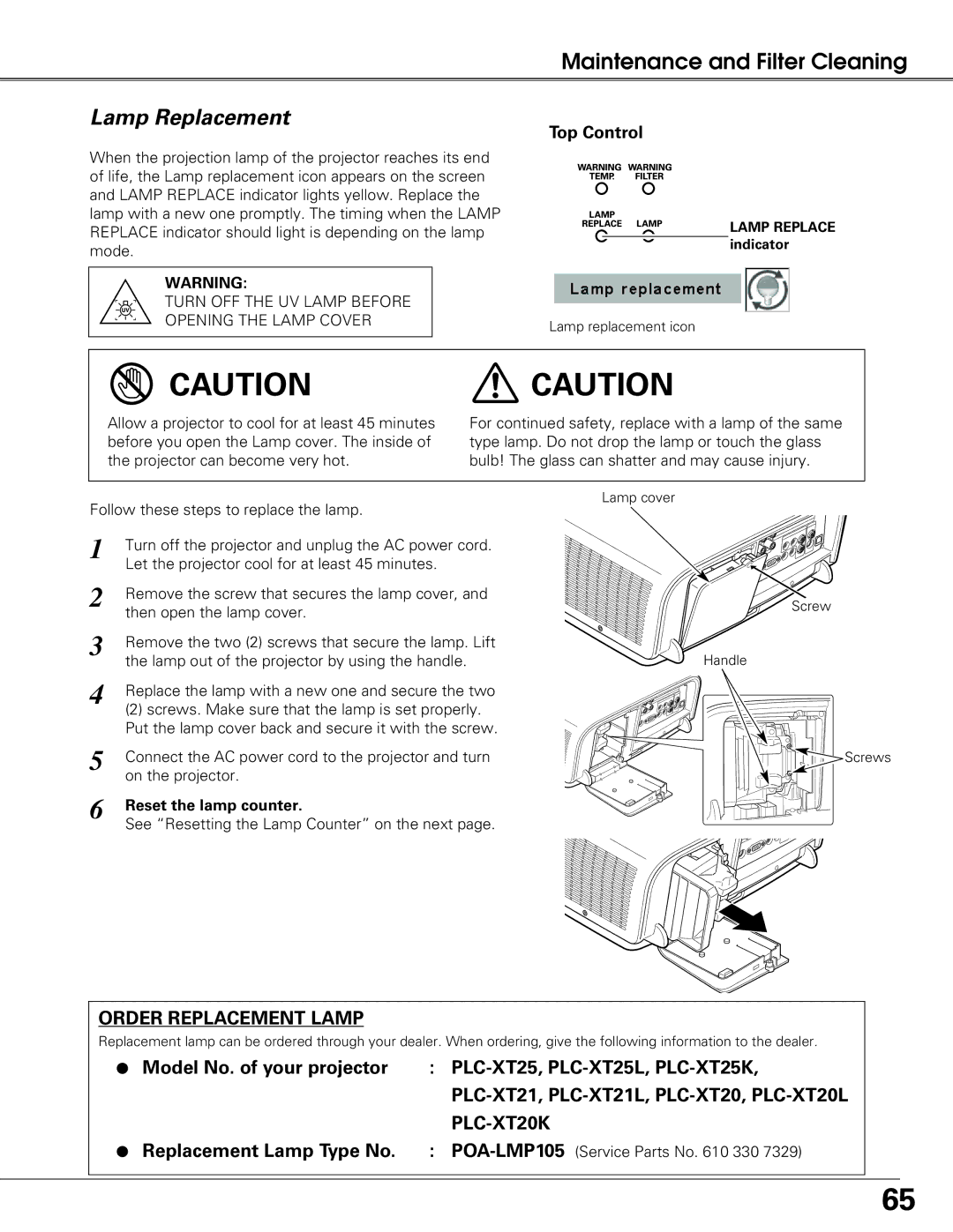
 Remote control
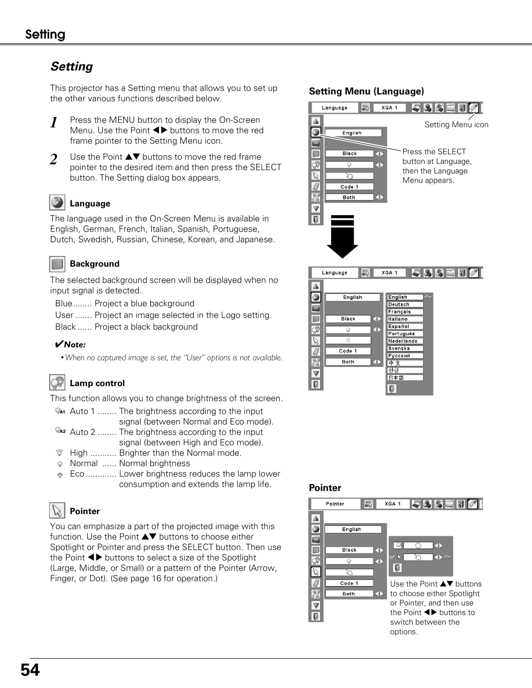
The eight different remote control codes (Code
The same code should set on both the projector and the remote control. For example, operating the projector in “Code 7”, the remote control code also must be switched to “Code 7”.
To change the code for the projector
Select a remote control code in this Setting Menu.
To change the code for the remote control:
Press and hold the MENU button and a number button
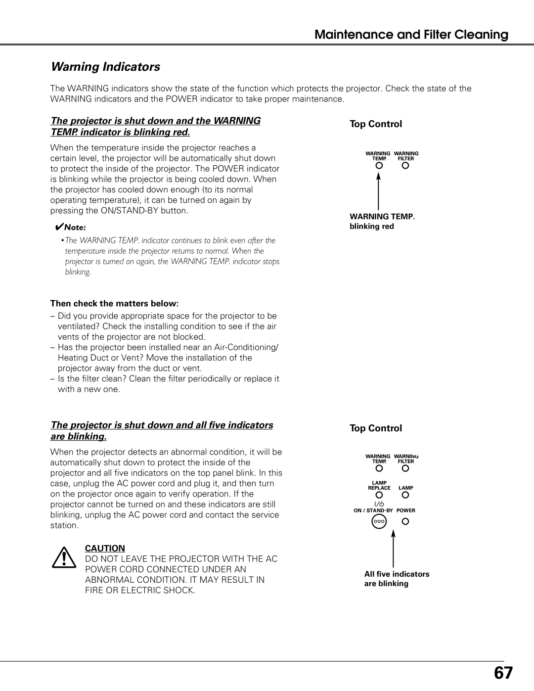
 RC sensor
Select a location of the infrared remote receiver of the remote control. See “Remote Control Operating Range” on page 18 for details.
Both | Activate both the front and back receiver. |
Front | Activate only the front receiver. |
Back | Activate only the back receiver. |
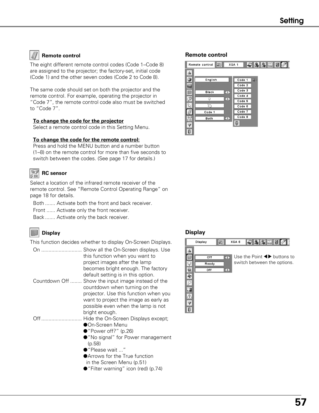
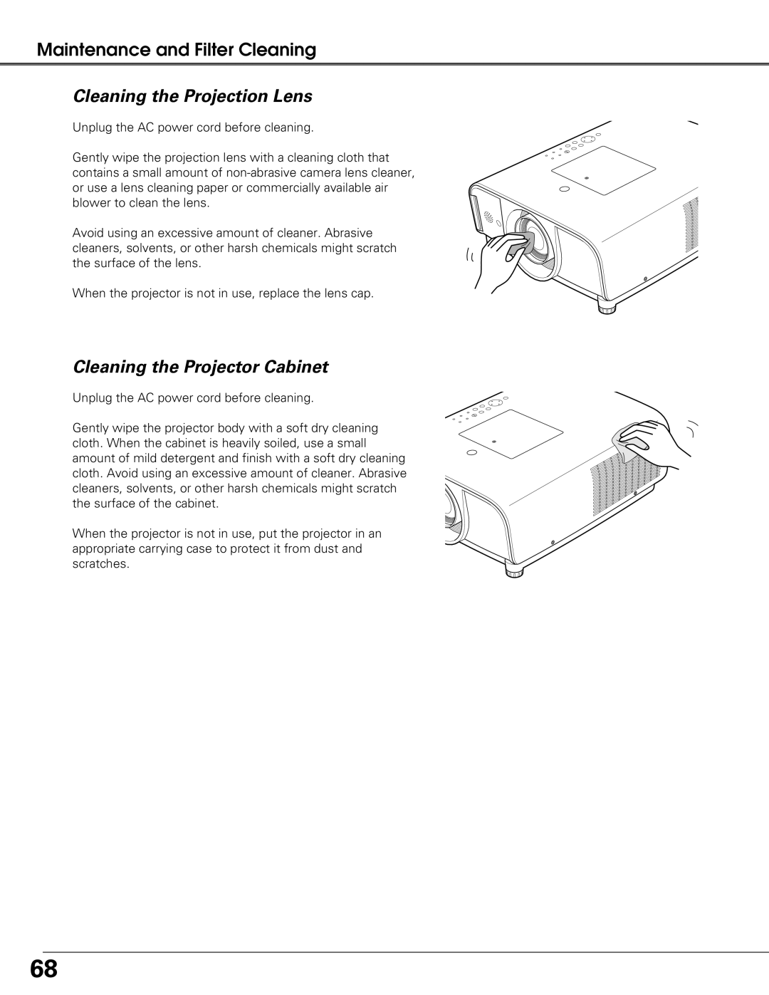
 Display
This function decides whether to display
On | Show all the |
| this function when you want to |
| project images after the lamp |
| becomes bright enough. The factory |
| default setting is in this option. |
Countdown Off | Show the input image instead of the |
| countdown when turning on the |
| projector. Use this function when you |
| want to project the image as early as |
| possible even when the lamp is not |
| bright enough. |
Off | Hide the |
| |
| ●“Power off?” (p.26) |
| ●“No signal” for Power management |
| (p.58) |
| ●“Please wait ...” |
| ●Arrows for the True function |
| in the Screen Menu (p.51) |
| ●“Filter warning” icon (red) (p.74) |
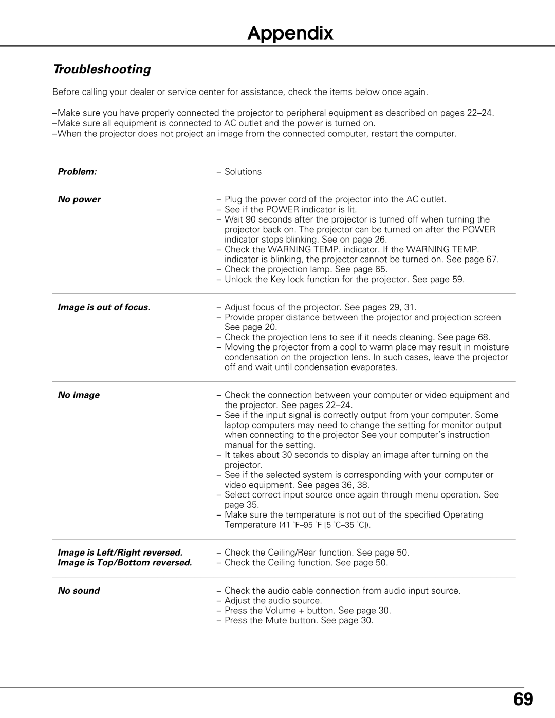
Remote control
Display
Use the Point 78 buttons to switch between the options.
57