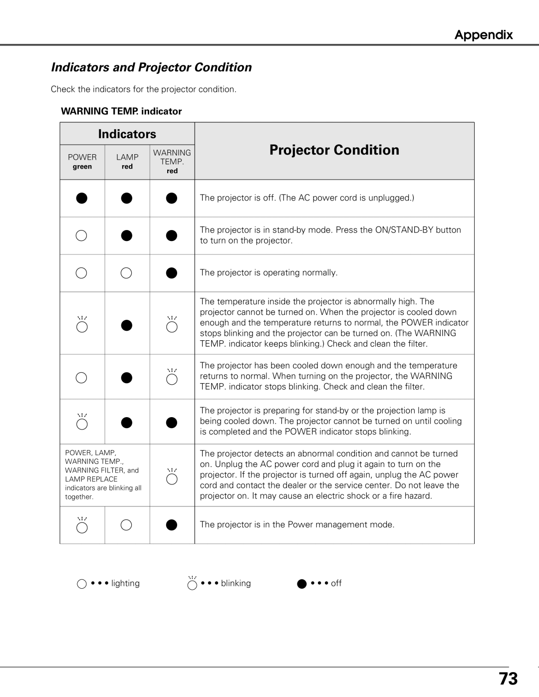
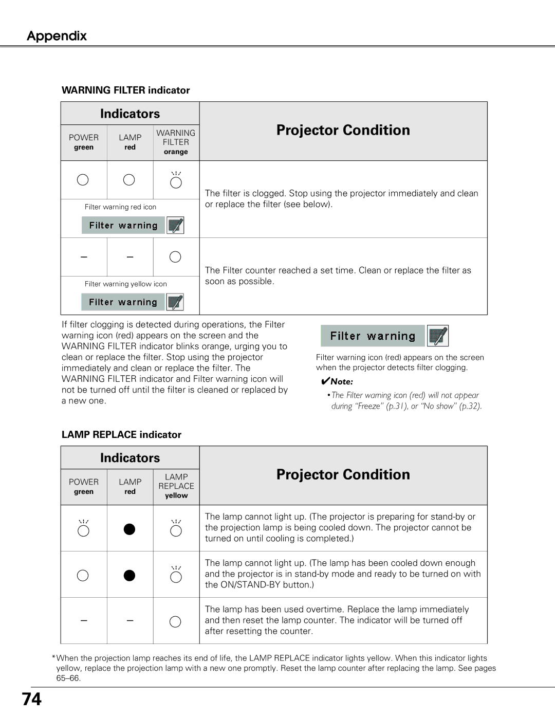
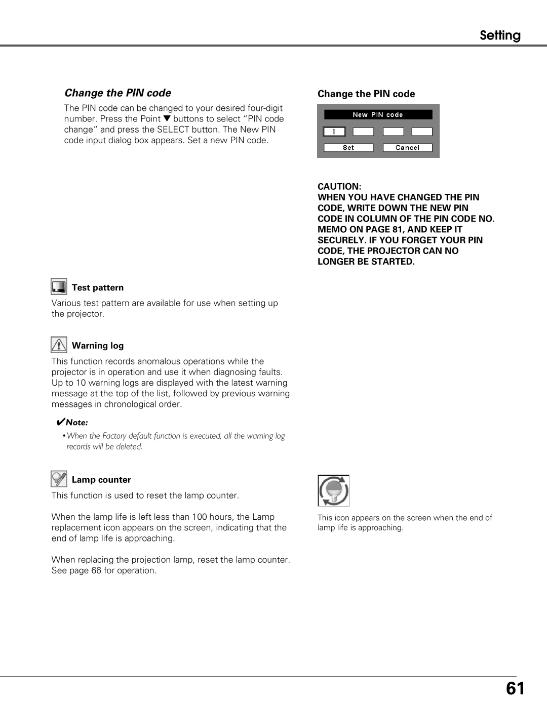
Sanyo PLC-XT20L*, PLC-XT25K, PLC-XT20K owner manual Change the PIN code, Test pattern, Lamp counter

Page 61

Setting

Change the PIN code

The PIN code can be changed to your desired four-digit number. Press the Point d buttons to select “PIN code change” and press the SELECT button. The New PIN code input dialog box appears. Set a new PIN code.

Test pattern

Various test pattern are available for use when setting up the projector.

Warning log

This function records anomalous operations while the projector is in operation and use it when diagnosing faults. Up to 10 warning logs are displayed with the latest warning message at the top of the list, followed by previous warning messages in chronological order.

Note:

•When the Factory default function is executed, all the warning log records will be deleted.
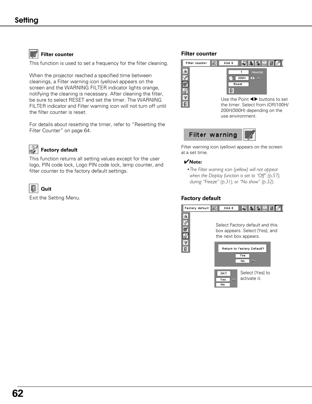
Lamp counter

This function is used to reset the lamp counter.

When the lamp life is left less than 100 hours, the Lamp replacement icon appears on the screen, indicating that the end of lamp life is approaching.

When replacing the projection lamp, reset the lamp counter. See page 66 for operation.

Change the PIN code

CAUTION:

WHEN YOU HAVE CHANGED THE PIN CODE, WRITE DOWN THE NEW PIN CODE IN COLUMN OF THE PIN CODE NO. MEMO ON PAGE 81, AND KEEP IT SECURELY. IF YOU FORGET YOUR PIN CODE, THE PROJECTOR CAN NO LONGER BE STARTED.

This icon appears on the screen when the end of lamp life is approaching.

61

Image 61
Contents Multimedia Projector Compact Design Power Management Features and DesignTable of Contents Risk of Electric Shock Do not Open To the OwnerSafety Instructions Top Control Air CirculationPositioning Precautions Installing the Projector in Proper DirectionsTransporting the Projector Moving the ProjectorAC Power Cord for the United Kingdom AC Power Cord for the United States and CanadaCompliance Front Back Bottom Part Names and FunctionsRear Terminal 4INFRARED Remote Receiver Back Reset buttonTop Control Remote Control 9RESET/ON/ALL-OFF switch 4P-TIMER button3MENU button 5D.ZOOM buttonPointer Function Laser Pointer FunctionSpotlight Pointer Remote Control Code Wireless Mouse OperationRemote Control Receivers and Operating Range Remote Control Battery InstallationAdjustable Feet Lens Installation InstallationRemoving the lens Attaching the lens to the projectorMoving the Lens Positioning the Projector for PLC-XT25/XT25K/XT21/XT20/XT20KProjector side AC outlet side Connecting the AC Power CordCables used for connection Connecting to a Computer Digital and Analog RGBConnecting to Video Equipment Video, S-Video Connecting to Video Equipment Component and RGB Scart Turning On the Projector Basic OperationSelected Input Source and Lamp Control PIN Code Input Dialog BoxTurning Off the Projector Remote Control How to Operate the On-Screen MenuOn-Screen Menu Menu Bar Lens Operation Operating with Projector ControlInformation Direct Operation Sound AdjustmentMenu Operation Operating with Remote Control No Show button Timer buttonKeystone button Input Selection Remote Control button operation Remote Control OperationInput Top Control OperationInput Menu Input Source SelectionRGB PC analog RGB Scart RGB PC digital Video ComponentVideo or S-Video Video System SelectionComponent AV System Menu Video or S-VideoHelpful Hints Computer AdjustmentSelecting Computer System Manually Computer System SelectionPC System Menu PC Adjust Menu Auto PC AdjustmentTo store adjustment parameters Auto PC AdjManual PC Adjustment To store the adjusted data To clear the adjusted dataMemo Image Mode Selection Image Menu Image Mode SelectionImage Adjustment Image Adjust Menu Image AdjustmentGamma SharpnessNoise reduction ProgressiveTo reset the adjusted data, select Reset and press Screen Adjustment Screen Menu Screen AdjustmentKeystone Screen Size Adjustment Computer Signals Screen Size Adjustment Video, Component Signals Setting Setting Menu Language SettingPointer Logo Capture Logo Logo and Logo PIN code lock settingsLogo select CaptureEnter a Logo PIN code Change the Logo PIN code lock settingChange the Logo PIN code Logo PIN code lockRemote control Display Power management Power management On start Key lock Fan controlEnter a PIN code Change the PIN code lock settingPIN code lock Test pattern Change the PIN codeLamp counter Factory default Factory defaultFilter counter Filter counterRecommendation Maintenance and Filter CleaningPage Replacement Lamp Type No. POA-LMP105 Service Parts No 330 Lamp ReplacementReset the lamp counter Model No. of your projectorLamp counter Resetting the Lamp CounterThen check the matters below Projector is shut down and all five indicators are blinkingCleaning the Projector Cabinet Cleaning the Projection LensAppendix TroubleshootingAppendix Input Menu TreeInformation Input Setting PC Adjust ScreenProjector Condition Indicators and Projector ConditionOr replace the filter see below Lamp Replace indicatorON-SCREEN Resolution Compatible Computer Specifications31.47 59.94 Technical Specifications Optional Parts AccessoriesPJ Link Notice USB Connector Series B Configurations of TerminalsTerminal Analog RGB Mini D-sub 15 pin Terminal Mini DIN 8-PINLogo PIN Code Lock No PIN Code Number MemoDimensions MZ7A-B