Yamaha CRW2200S manual Table of Contents

Page 8

Table of Contents


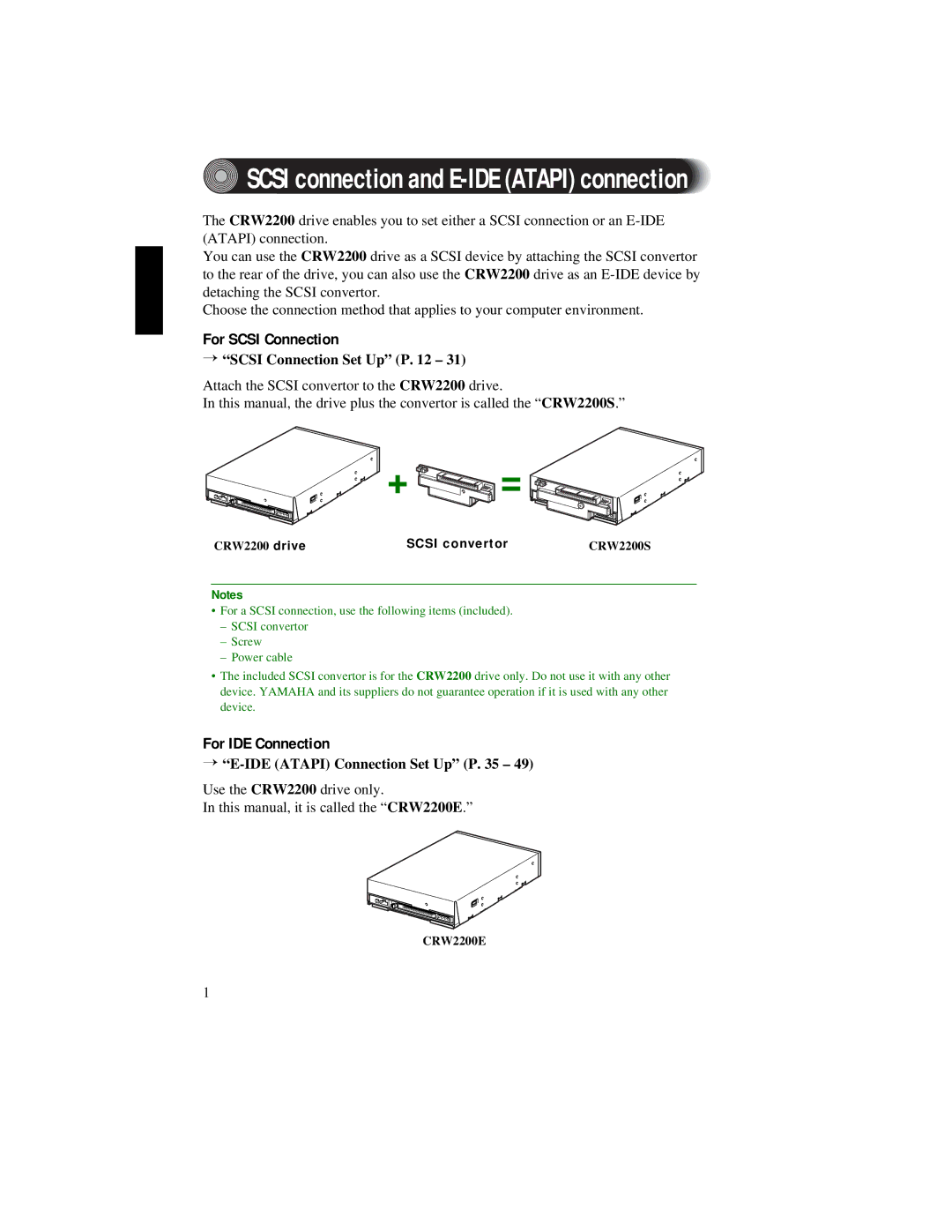
SCSI connection and E-IDE (ATAPI) connection

.............................. 1

Introduction

2

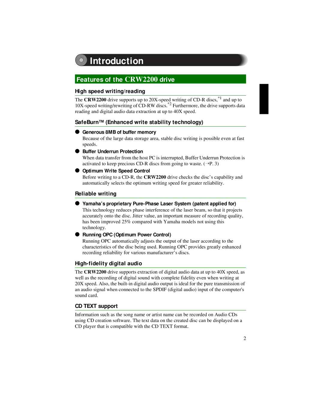
Features of the CRW2200 drive

2

Before Use

4

System Requirements

4

Supported Discs

5

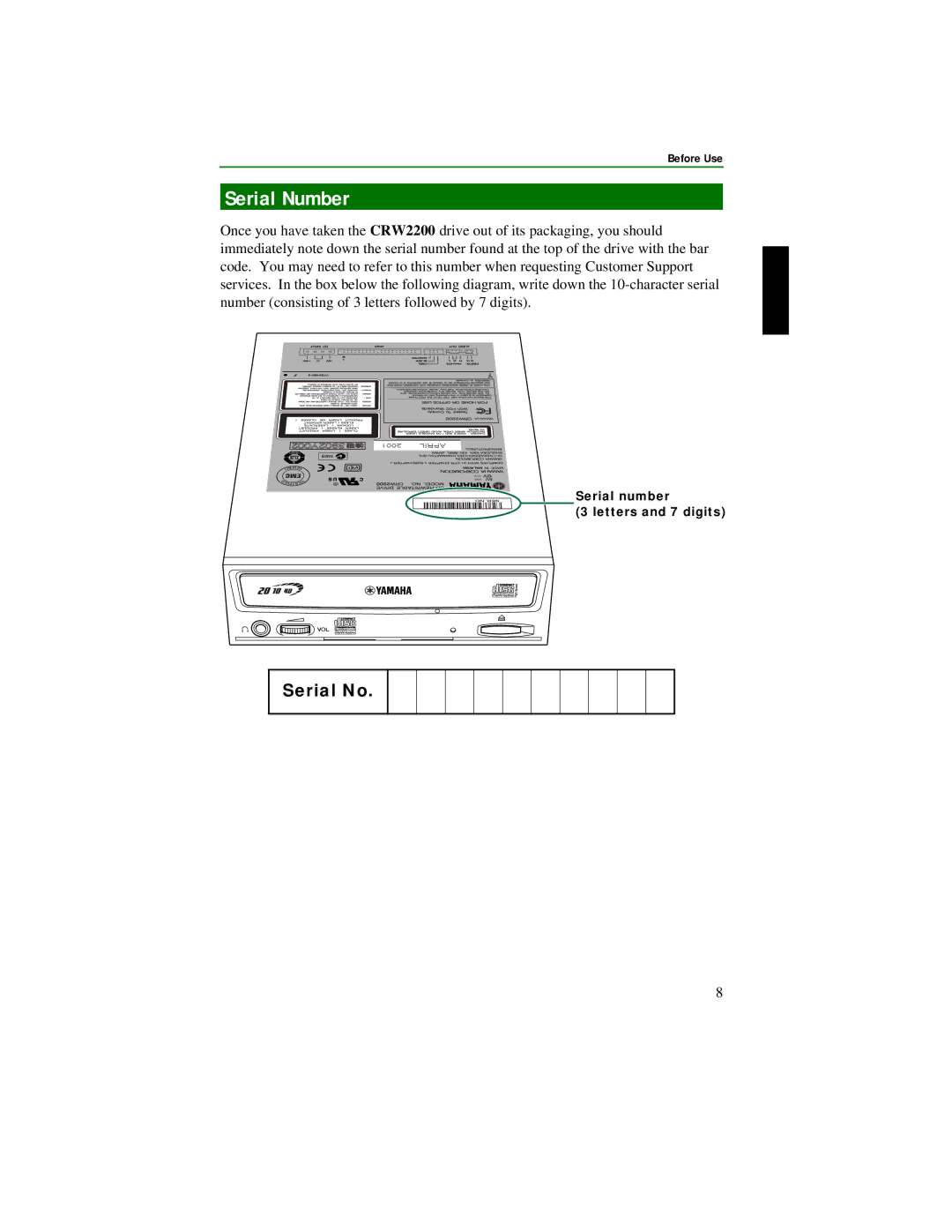
Serial Number

8

Front and Rear of Unit

9

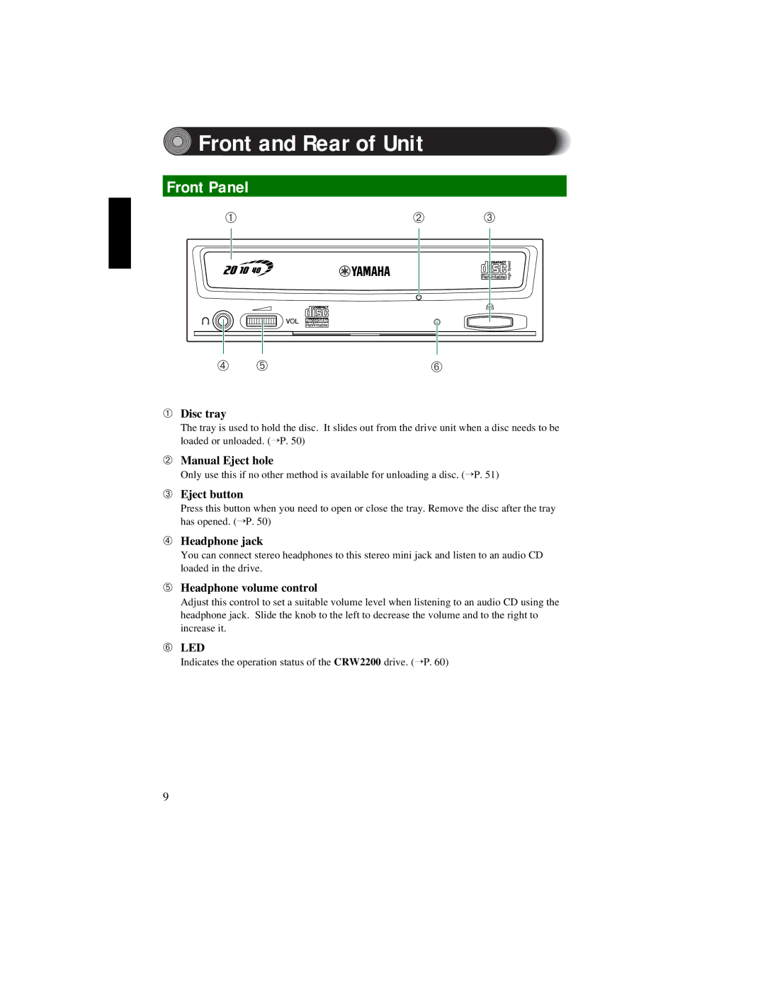
Front Panel

9

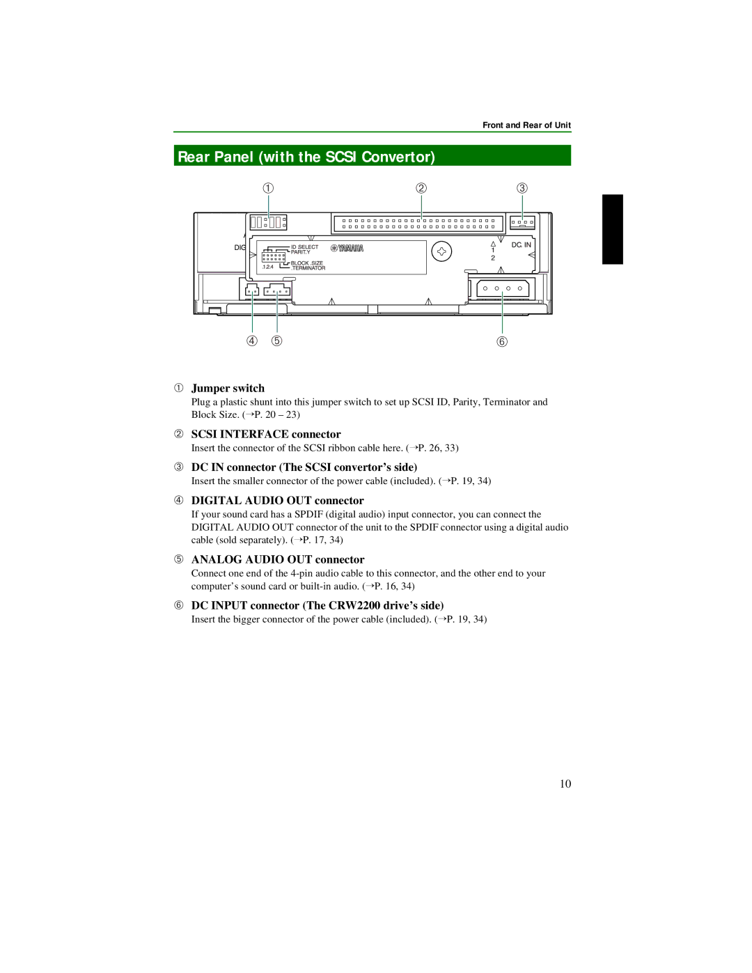
Rear Panel (with the SCSI Convertor)

10

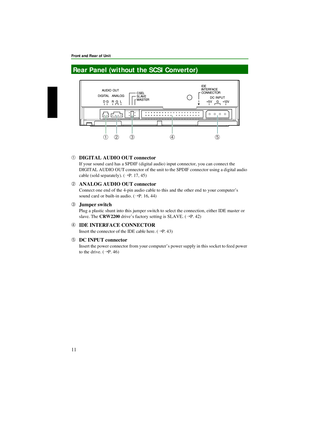
Rear Panel (without the SCSI Convertor)

11

SCSI Connection Set Up

12

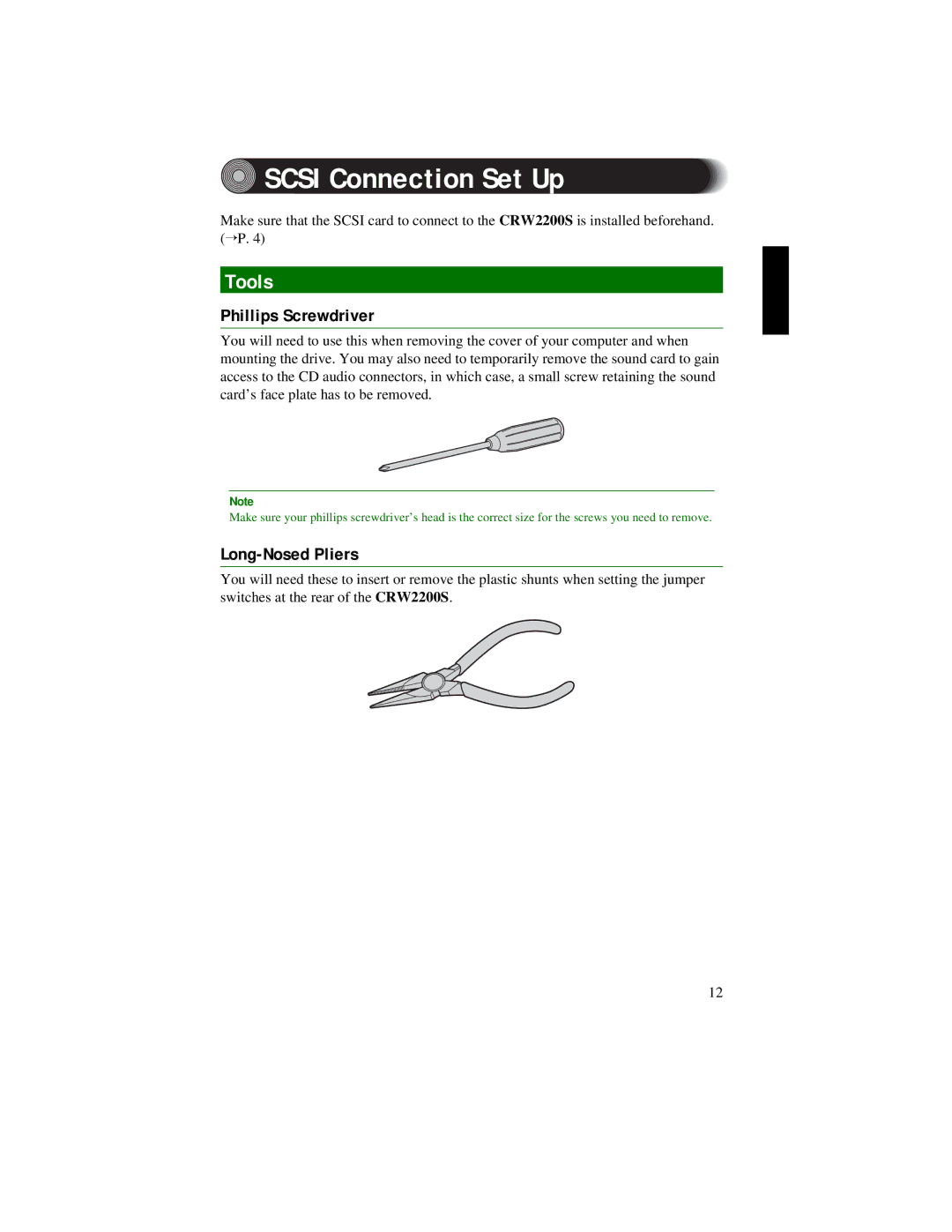
Tools

12

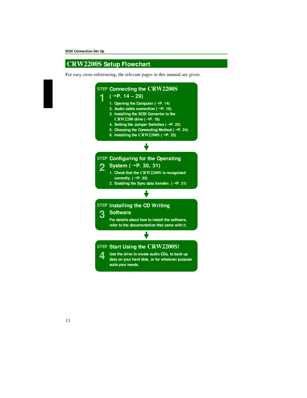
CRW2200S Setup Flowchart

13

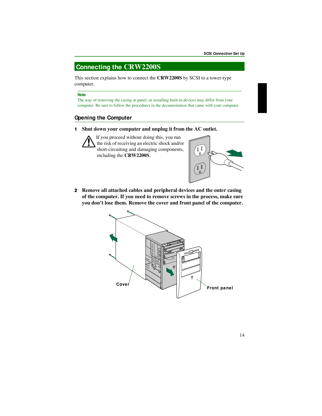
Connecting the CRW2200S

14

Removing the SCSI convertor

32

Tools

32

Removing the SCSI convertor

32

E-IDE (ATAPI) Connection Set Up

35

Tools

35

CRW2200E Setup Flowchart

36

Connecting the CRW2200E

37

Operation

50

Loading a Disc

50

Ejecting a Disc

50

Ejecting a Disc in an Emergency

51

Troubleshooting

52

Appendix

57

Writing Modes

57

About firmware

59

LED Indicator Messages

60

CRW2200 Specifications

60

Index

64

©2001 YAMAHA CORPORATION. All Rights Reserved.

This document may not, in whole or in part, be copied, photocopied, reproduced, translated, transmitted, or reduced to any electronic medium of machine readable form without prior consent in writing from Yamaha.

Windows is a registered trademark of Microsoft Corporation. UNIX is a registered trademark of UNIX System Laboratories. SafeBurn™ is a trademark of Yamaha Corporation.

All other trademarks are the property of their respective companies.

v
Image 8
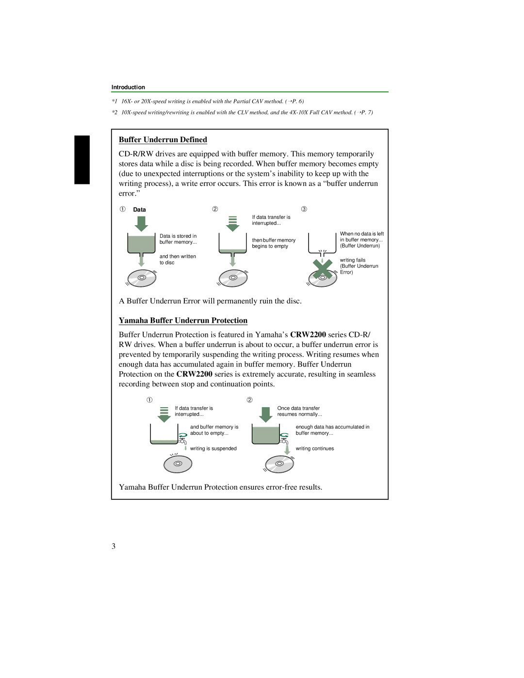
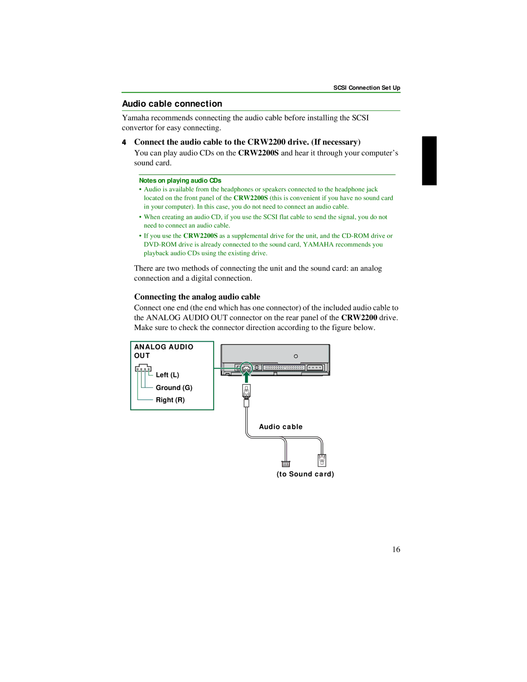
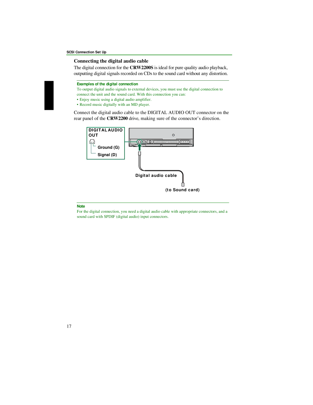
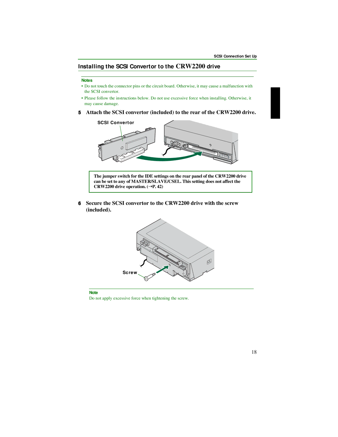
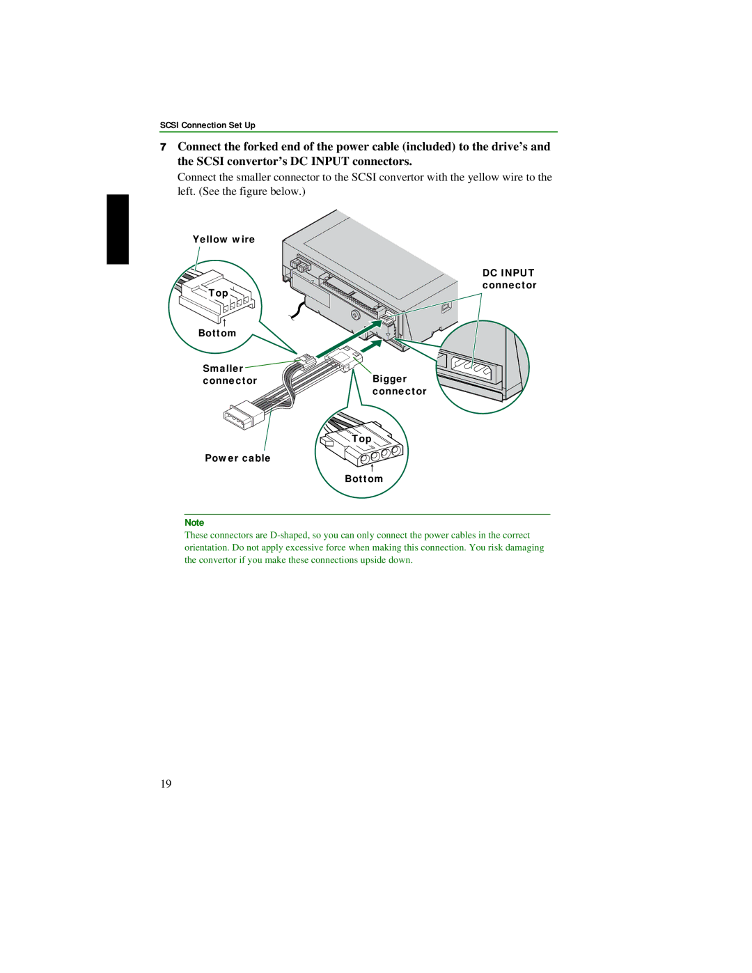
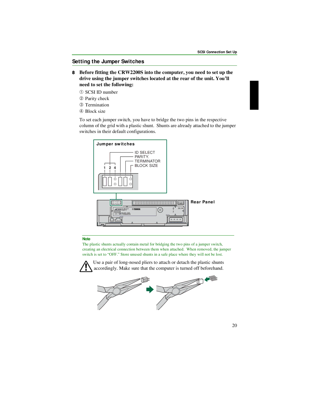
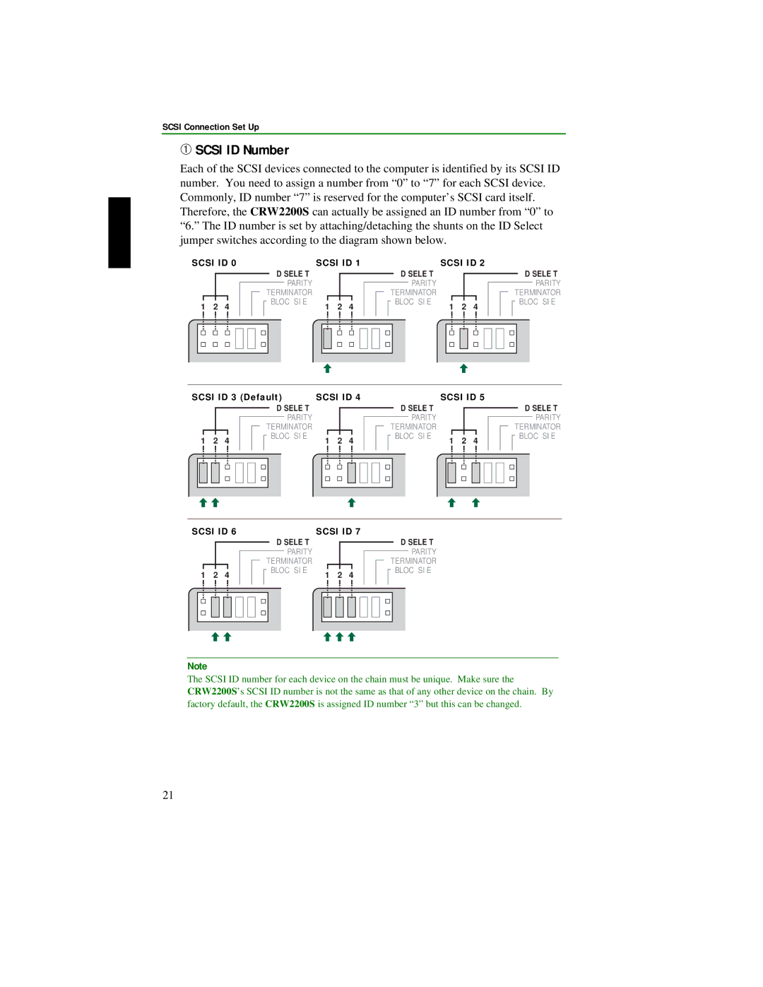
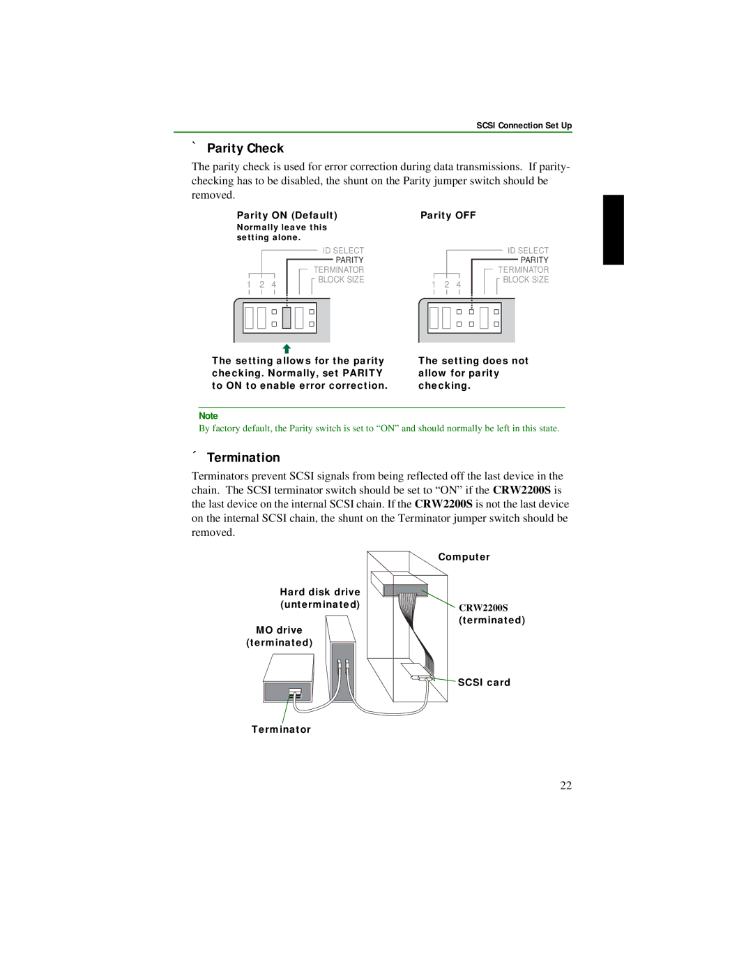
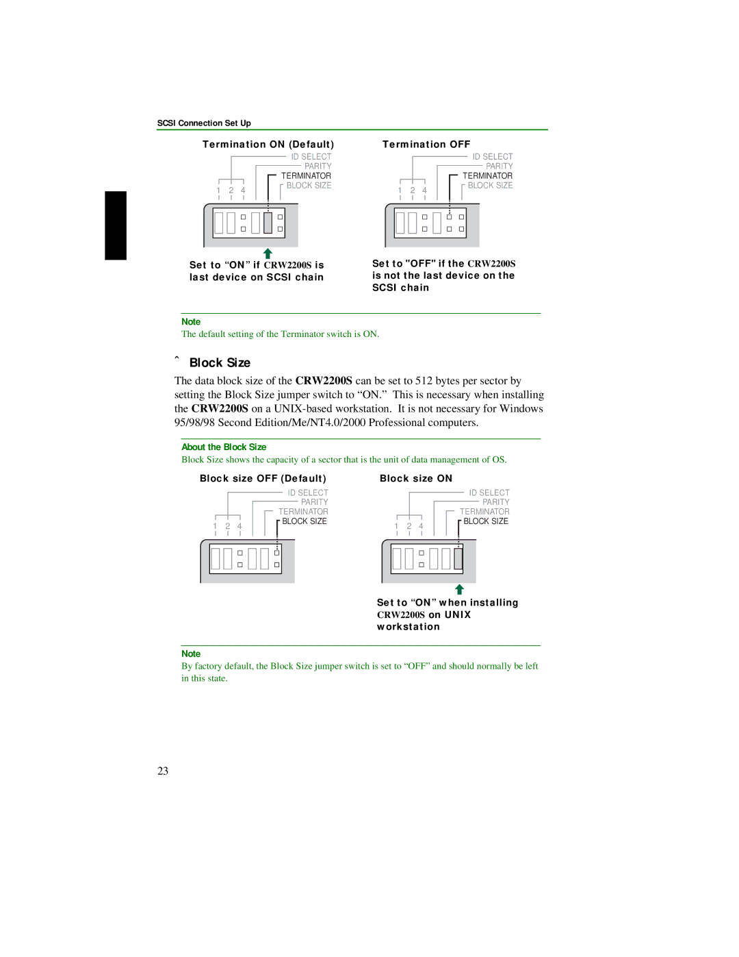
Contents Page FCC Information U.S.A Achtung English Safety Precautions Iii Warranty Table of Contents Scsi convertor → Scsi Connection Set Up P→ E-IDE Atapi Connection Set Up P Features of the CRW2200 drive IntroductionIntroduction Buffer Underrun DefinedYamaha Buffer Underrun Protection These are also required for Scsi connection Before UseSystem Requirements Supported Discs CD-R discs*1CD-RW discs*2 High Speed CD-RW discs*3About CD-ROMs About Partial CAV Constant Angular VelocityAbout 10X-speed writing/rewriting of a High Speed CD-RW disc Serial Number Serial number Letters and 7 digitsFront and Rear of Unit Front PanelRear Panel with the Scsi Convertor ➀ Digital Audio OUT connector ➁ Analog Audio OUT connector➂ Jumper switch ➄ DC Input connectorScsi Connection Set Up ToolsPhillips Screwdriver Long-Nosed PliersCRW2200S Setup Flowchart Scsi Connection Set UpConnecting the CRW2200S Opening the ComputerShut down your computer and unplug it from the AC outlet Cover Front panelDischarge any static charge Connecting the analog audio cable Audio cable connectionConnect the audio cable to the CRW2200 drive. If necessary Left L Ground G Right R Audio cable To Sound cardConnecting the digital audio cable Ground G Signal D Digital audio cable To Sound cardInstalling the Scsi Convertor to the CRW2200 drive ScrewYellow wire DC InputRear Panel Setting the Jumper SwitchesJumper switches ➀ Scsi ID Number Scsi ID➁ Parity Check ➂ TerminationBlock size OFF Default Block size on Set to on when installing➃ Block Size WorkstationCD-ROM drive As a replacement driveChoosing the Connection Method Inch drive bay slot Front cover Installing the CRW2200SAudio cable Pin IDE cable Pin power cable Colored line connector Scsi connector 50-pin Scsi flat cable MotherboardDigital audio cable Sound card SpdifTop Bottom Power cable Pin power cable Reconnect the computer to the AC outlet and turn it on Configuring for the Operating System For Windows NTInstalling the CD Writing Software Install the CD writing softwareRemoving the Scsi convertor Removing the Scsi convertorAudio cable Pin Scsi flat cable Pin power cable Removing the Scsi convertorRemove the Scsi convertor from the CRW2200 drive IDE Atapi Connection Set Up CRW2200E Setup Flowchart IDE Atapi Connection Set UpConnecting the CRW2200E Choosing the Connection Method Slave Motherboard Primary Master Secondary SlaveMaster Typical IDE-type hardware installationAbout IDE Connecting examples Example-1 As secondary slave For supplemental driveIDE Atapi Connection Set Up About the Csel jumper switch Rear Panel Master Slave factory settingInstalling the CRW2200E As an supplemental driveConnect the audio cable. If necessary Ground G Signal D Digital audio cable Top DC Input connector Bottom Pin power cable Configuring for the Operating System About DMA Settings Setting of Transfer Mode About DMA Ejecting a Disc OperationLoading a Disc Manual Eject hole Paper Clip Ejecting a Disc in an EmergencyOperation Troubleshooting Yamaha CD-R/RW Drives web site URL EuropeTroubleshooting Disc keeps being ejected Properties setting of the CRW2200S Setting of the Windows Media PlayerBuffer Underrun error message is displayed Appendix Writing ModesDisc-at-Once DAO Track-at-Once TAOAppendix Session-at-Once SAOPacket Writing About firmware URL for Yamaha CD-R/RW Drives web sites EuropeLED Indicator Messages Status Ndicator essages LED olorCD-RW CRW2200 drive CRW2200 series complies with the following specifications Symbols IndexPhillips Screwdriver 12, 32 EUROPE, Eastern Europe Russia