Bosch Appliances XD Alarm Connections, Line In / Microphone MIC, Line Out/Speaker SPK, Selection

Page 34

34 en Configuration Using a Web Browser

VIP XD


Line In / Microphone (MIC)

You can set the audio signal gain for the line and microphone input. Make sure that the display does not go beyond the green zone during modulation.

Line Out/Speaker (SPK)

You can set the gain of the line and loudspeaker output. Make sure that the display does not go beyond the green zone during modulation.

Selection

Click one of the option boxes and then click Set to display the level of the respective audio input for orientation and to set the gain.
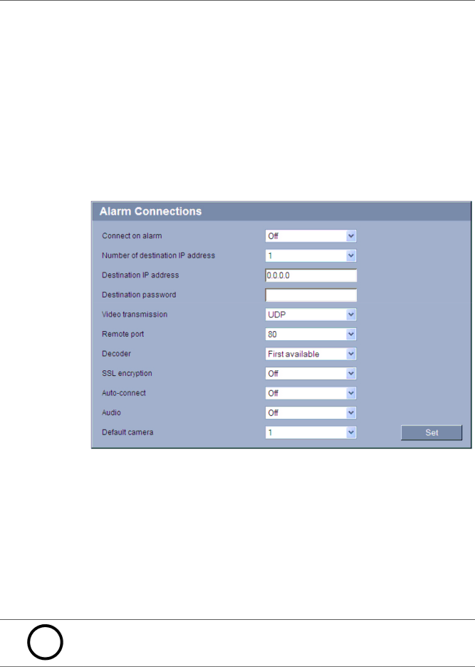
5.11

Alarm Connections

You can select how the VIP XD responds to an alarm. In the event of an alarm, the unit can automatically connect to a pre-defined IP address. You can enter up to ten IP addresses to which the VIP XD will connect in sequence in the event of an alarm, until a connection is made.

Connect on alarm

Select On so that the VIP XD automatically connects to a predefined IP address in the event of an alarm.

By setting Follows input 1, the VIP XD automatically connects to a remote station and holds the connection as long as an alarm exists on alarm input 1. This option can also be used to connect two units (sender and receiver) via a switch connected to the VIP XD. You do not need a computer to make the connection in this case.

NOTICE!

i In the default setting, Stream 2 is transmitted for automatic connections. Bear this fact in mind when assigning the profile to the corresponding sender.

DOC V4.0 2009.06

Installation and Operating Manual

Bosch Security Systems

Image 34
Contents VIP XD Page Table of Contents Operation Maintenance and UpgradesSpecifications AppendixConventions in this Manual PrefaceAbout this Manual Intended UseEU Directives Rating PlateMaintenance and Repair Safety InformationInstallation and Operation Electric Shock HazardEn Safety Information Product Description Scope of DeliveryGeneral Requirements Additional Configuration RequirementsSystem Requirements Additional Operational RequirementsOverview of Functions Summary HttpsConnections on the Front Panel Connections on the Rear Panel LED4Installation 1Preparations2Connections Network Alarm InputsData Interface Relay Output Maximum rating of the relay contact is 30 V and 2 a SelvPower Supply Power On/Power OffSetup Using the Configuration Manager Installing the ProgramReboot Configuring the VIP XDClick Unit network settings... in the popup menu Additional ParametersInstalling Mpeg ActiveX Configuration Using a Web Browser1Connecting System RequirementsEstablishing the Connection Maximum Number of ConnectionsProtected VIP XD Protected NetworkNavigation Configuration MenuMaking Changes Device ID 4Password3Identification Device name5Date/Time Time server IP address Daylight saving timeTime server type Company logo 6AppearanceWebsite language Device logoStandard Decoder ProfileMonitor name Overscan8VGA VGA screen sizeBorder top / bottom / left / right ResolutionRefresh rate Horiz. spacing / Vert. spacingHorizontal synchronization / Vertical synchronization Resetting ChangesDetails Border colorMonitor Display Audio Audio Version OnlyLine In / Microphone MIC Alarm ConnectionsConnect on alarm Line Out/Speaker SPKDestination IP address Destination passwordNumber of destination IP address Video transmissionAuto-connect Default cameraAudio Audio Version Only Name Audio Alarm Audio Version OnlyAudio alarm ThresholdAlarm E-Mail Destination address FormatStandard E-mail Sender nameAlarm Task Editor Relay Alarm InputsAlarm input Idle stateOff Operating mode10 s Relay follows Connection17 COM1 Network Subnet mask Automatic IP assignmentIP address Gateway addressRCP+ port Interface mode ETHEnable DynDNS Telnet supportStatus AdvancedSnmp host address / 2. Snmp host address Snmp traps AuthenticationEncryption IdentityMaintenance FirmwareUpload 192.168.0.32/resetMaintenance log DownloadLicenses System OverviewFunction Test 6Operation En Operation Protected VIP XD Preview 2The ConnectionsMonitor Connections Between the Sender and Receiver Selecting Decoder for Quad View Controlling ConnectionsMulticast scan Connecting with a Terminal Program ConnectingConnecting on Alarm Hardware Connections Between Video Servers5Operation with Management Software Testing the Network Connection Maintenance and Upgrades2Unit Reset Repairs Transfer and DisposalMalfunction Possible causes Recommended solution 1Troubleshooting8Appendix En AppendixVIP XD Network Connection LEDs3Processor Load Operating Status LEDTerminal Block Contact RS-232 mode RS-422 mode RS-485 modeSerial Interface Pin AssignmentCommunication with Terminal Program Configuring the TerminalCommand Inputs Data TerminalAssigning an IP Address 8Copyrights En Appendix Unit SpecificationsAudio Version Only Protocols/Standards PAL, NtscGlossary Icmp GOPHttp IeeeMPEG-4 MIBMPEG-2 MSSSntp SniaSnmp SSLEprom IndexRadius Serial number Serial port function Signal source SMS Page Bosc h Sicherheitssysteme GmbH
Related manuals
Manual 7 pages 2.9 Kb