3.4Checking Magnetron Heater Voltage
Note: This confirmation/adjustment should only be performed by a qualified service technician.
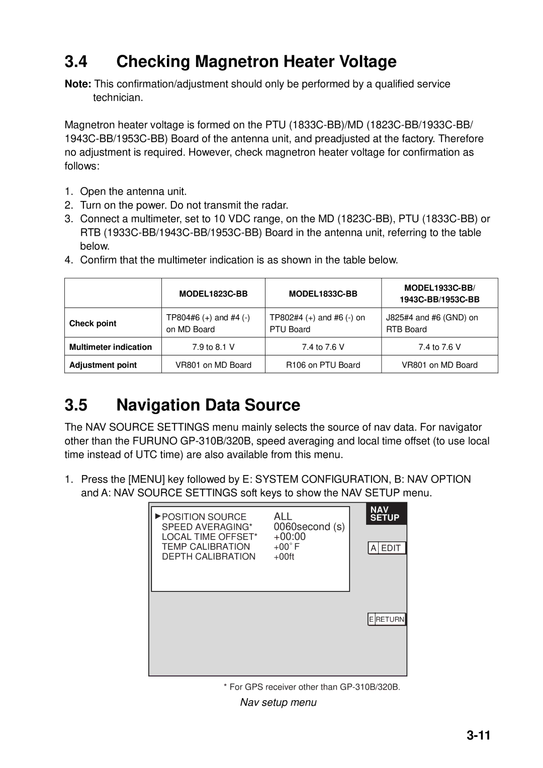
Magnetron heater voltage is formed on the PTU
1.Open the antenna unit.
2.Turn on the power. Do not transmit the radar.
3.Connect a multimeter, set to 10 VDC range, on the MD
4.Confirm that the multimeter indication is as shown in the table below.
|
|
|
| |
| ||||
|
|
| ||
|
|
|
| |
Check point | TP804#6 (+) and #4 | TP802#4 (+) and #6 | J825#4 and #6 (GND) on | |
on MD Board | PTU Board | RTB Board | ||
| ||||
|
|
|
| |
Multimeter indication | 7.9 to 8.1 V | 7.4 to 7.6 V | 7.4 to 7.6 V | |
|
|
|
| |
Adjustment point | VR801 on MD Board | R106 on PTU Board | VR801 on MD Board | |
|
|
|
|
3.5Navigation Data Source
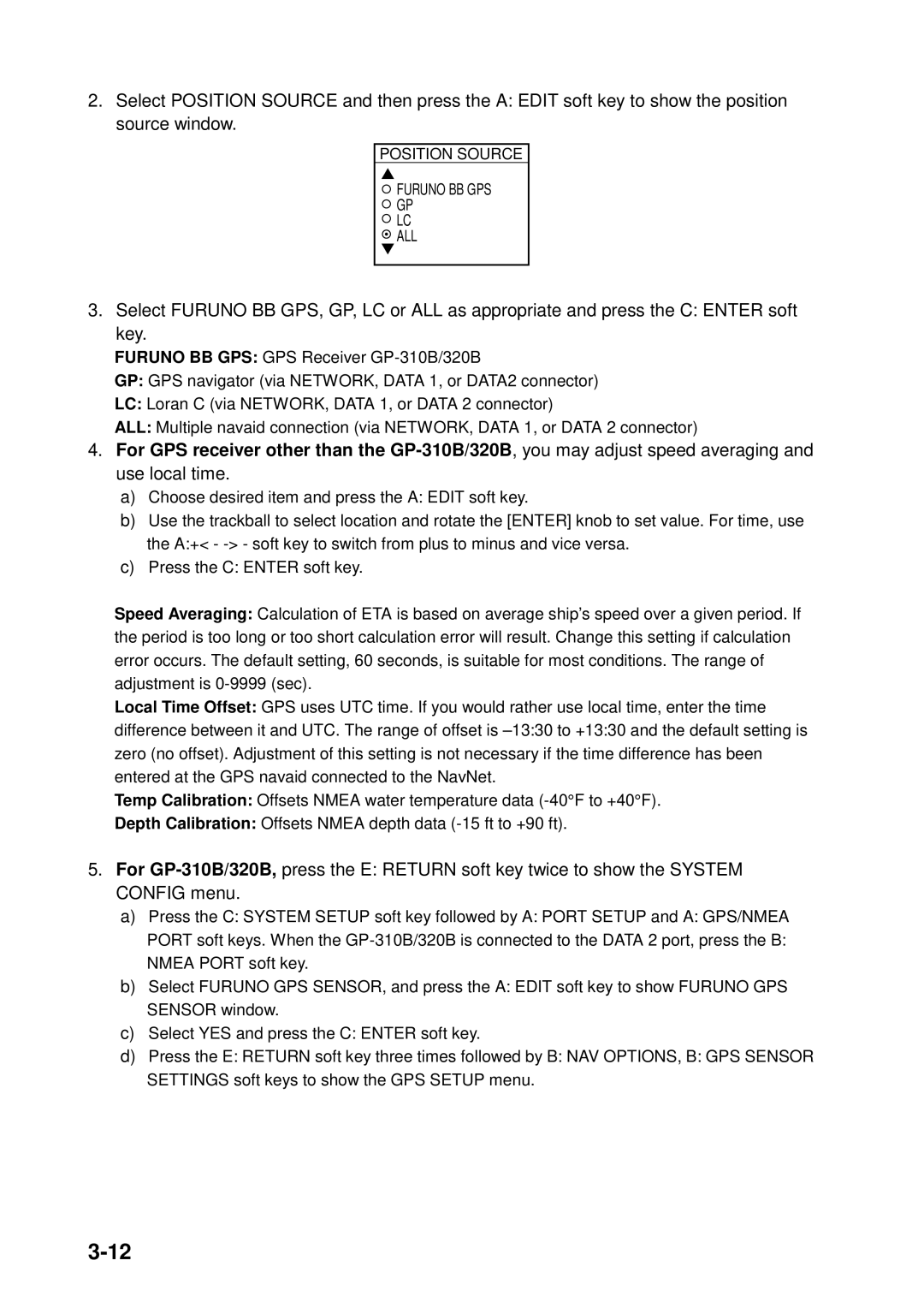
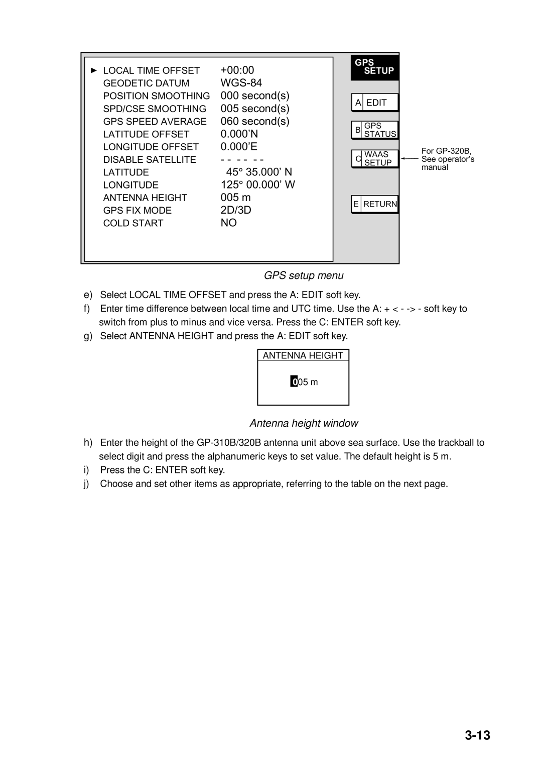
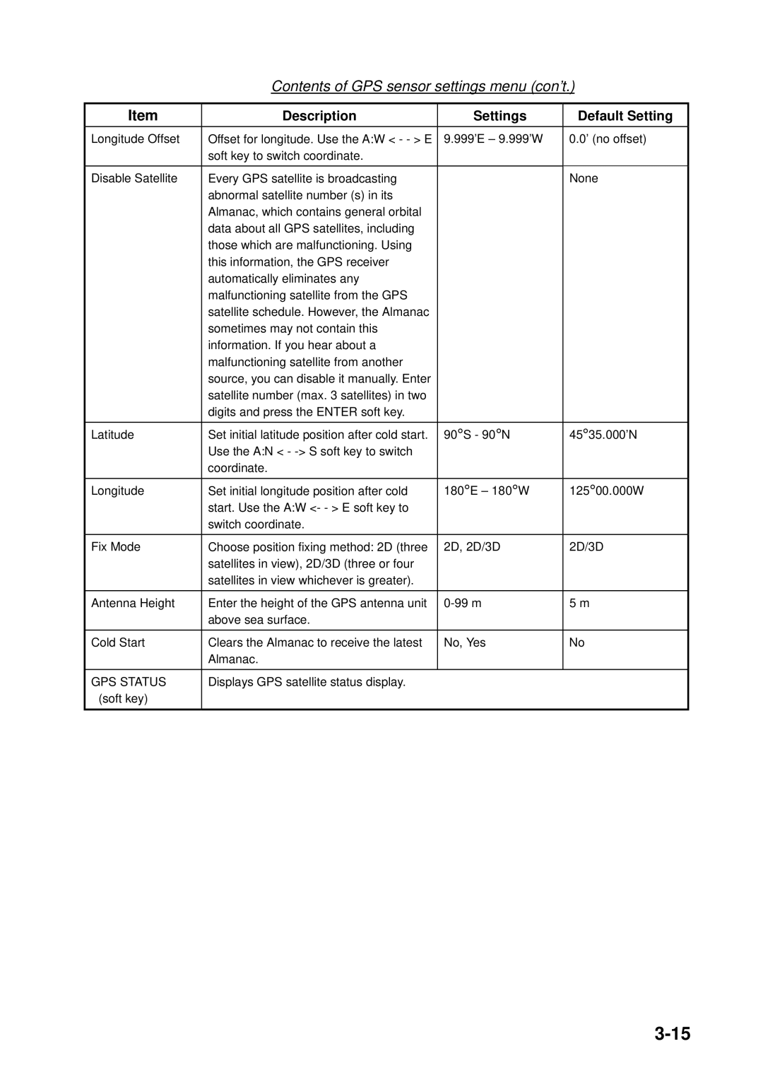
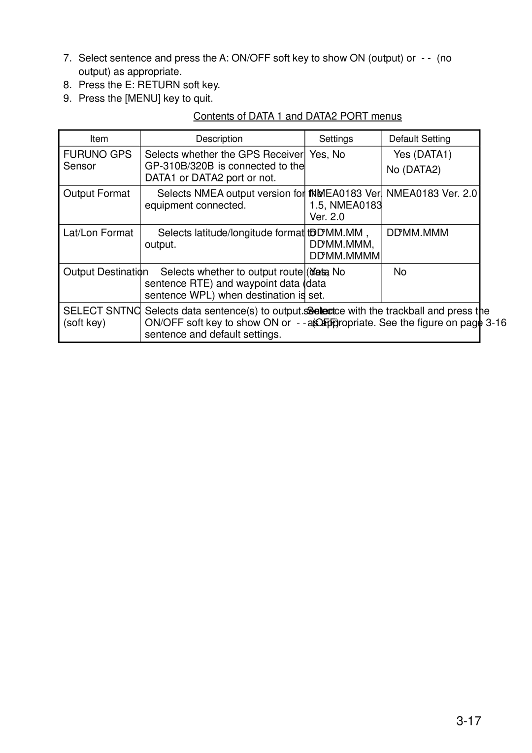
The NAV SOURCE SETTINGS menu mainly selects the source of nav data. For navigator other than the FURUNO
1.Press the [MENU] key followed by E: SYSTEM CONFIGURATION, B: NAV OPTION
and A: NAV SOURCE SETTINGS soft keys to show the NAV SETUP menu.
POSITION SOURCE | ALL | NAV |
SETUP | ||
SPEED AVERAGING* | 0060second (s) |
|
LOCAL TIME OFFSET* | +00:00 |
|
TEMP CALIBRATION | +00 F | A EDIT |
DEPTH CALIBRATION | +00ft |
|
|
| E RETURN |
* For GPS receiver other than
