SPS 4001B
Instruction Manual
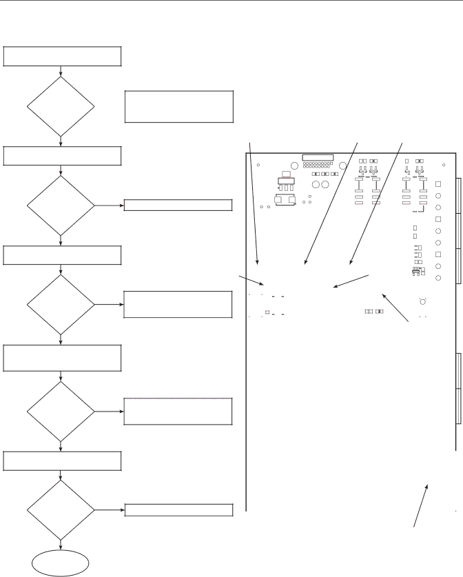
Figure 5-1. SPS 4001B Troubleshooting Flowchart (Sheet 1 of 2)
SYMPTOM — NO CALIBRATION GAS FLOW
CHECK ALL WIRING BETWEEN
OXYMITTER 4000 AND SPS 4001B
IS
WIRING
PROPERLY NO CONNECTED ![]()
AND
SECURE?
PROPERLY CONNECT WIRING OR SECURE LOOSE WIRING CONNECTIONS; REPLACE DAMAGED WIRING.
YES
CHECK LOGIC I/O SETTING VIA HART/AMS.
IS
LOGIC I/ONO
SET
PROPERLY?
YES
DISCONNECT CAL GAS INPUT LINES AT MANIFOLD.
SET LOGIC I/O VIA HART/AMS.
TP1
J5 |
|
|
|
|
|
|
|
|
|
|
| J6 |
|
| J3 |
|
|
|
|
|
|
|
|
|
|
|
|
| C14 |
|
|
|
|
|
|
|
|
|
|
|
|
|
|
|
|
| R13 |
| C16 | R16 |
H3 |
|
|
|
| TP31 |
|
|
|
| J7 | TP32 |
|
|
| H4 | |
|
|
|
|
|
|
|
|
|
|
|
| |||||
|
|
|
|
|
|
|
|
|
|
|
| D8 | Q1 |
| D10 | Q2 |
|
|
|
|
|
|
|
|
|
| R26 |
| K1 |
|
| K2 |
|
|
|
|
|
|
| R24 | R25 |
|
|
|
|
|
| |||
|
|
|
|
|
|
|
|
|
|
|
|
|
| |||
|
|
| U11 |
|
|
|
|
|
|
|
|
|
|
|
| |
|
|
|
|
|
| TP30 |
|
| TP29 |
|
|
|
|
|
| |
|
|
|
|
|
| TP22 |
|
|
|
|
|
|
|
|
|
|
|
|
|
|
|
| TP26 |
|
|
|
|
|
|
|
|
|
|
TP23 |
| TP25 |
|
|
| TP19 |
|
|
|
|
|
|
|
|
|
|
|
|
|
| TP24 |
|
|
|
|
|
|
|
|
|
| ||
|
|
| TP28 | C22 |
|
|
|
|
|
|
|
|
|
| ||
|
|
| TP18 |
|
|
|
|
|
|
|
|
|
| |||
|
| TP20 |
|
|
|
|
|
|
|
|
|
|
|
|
| |
|
|
|
|
| TP27 | C20 |
|
|
|
|
|
|
|
| ||
TP21 |
|
|
|
| C23 |
|
|
|
|
|
|
|
| |||
|
|
|
| TP16 |
|
|
|
|
|
|
|
|
|
| ||
|
| TP17 |
|
|
|
|
|
|
|
|
|
|
|
|
| |
|
|
|
|
|
|
|
| U9 |
|
|
|
|
|
|
| |
R23 |
|
|
|
|
|
|
|
| U5 | R18 |
|
|
|
|
| |
|
|
|
|
|
|
|
|
|
|
|
|
|
|
|
| |
|
| R28 |
|
|
|
|
|
|
|
|
|
|
|
|
| L5 |
|
| U10 |
|
|
|
|
|
| C18 |
|
|
|
| R17 |
| |
|
|
|
|
|
|
|
|
|
|
|
|
| L4 | |||
| C21 |
|
|
| U8 |
|
|
|
|
|
|
| U6 |
| ||
|
|
|
|
|
|
|
| R20 | U7 |
|
|
| ||||
|
|
|
|
|
|
|
|
|
|
|
| D11 |
|
| ||
|
|
|
|
| C19 |
|
|
|
|
|
|
|
|
| ||
TP15 | TP13 TP9 | TP6 |
|
|
|
| R22 |
|
|
|
|
|
| |||
TP5 |
|
|
|
|
|
|
| R27 |
| |||||||
|
|
|
|
| TP12 |
|
|
|
|
|
|
| ||||
|
|
|
|
|
| TP8 |
|
|
|
|
|
|
|
| ||
|
|
|
|
|
|
|
|
|
|
|
|
|
|
| L3 | |
|
|
|
|
|
|
|
| C13 | U3 |
|
|
|
|
| R14 |
|
|
|
|
|
|
|
|
|
| R12 | Q5 |
|
|
|
| L2 | |
TP14 | TP11 | TP7 | R19 | TP4 |
|
|
|
|
|
|
|
| ||||
|
|
|
|
|
|
|
|
| ||||||||
|
|
|
|
|
|
|
|
|
|
|
|
|
| C17 | ||
|
|
|
|
|
| TP10 |
|
|
|
|
|
|
|
| R15 | |
|
|
|
|
|
|
|
|
|
|
|
|
|
|
|
| U4 |
|
|
|
|
|
|
|
|
|
|
|
|
| TP2 |
|
| C15 |
|
|
|
|
| Q3 |
|
|
|
|
|
|
|
| D9 |
| |
|
|
|
|
|
|
|
|
|
|
|
|
|
| D14 |
| |
J5 |
| TP1 |
|
| J6 | Q4 |
|
| J3 |
|
|
|
|
|
| |
|
| D12 |
|
|
| R21 TP2 |
|
|
|
|
|
|
| |||
|
|
| D13 |
|
|
|
|
|
|
|
|
| ||||
D1 |
|
|
|
|
|
|
|
|
|
|
|
|
|
|
| |
|
|
|
|
| C1 |
|
|
|
|
|
|
|
| TP3 |
|
|
IS THERE
FLOW?
NO
REPLACE CLOGGED CAL GAS LINE BETWEEN CAL GAS CYLINDER AND MANIFOLD.
| R1 |
|
|
|
|
|
|
|
|
| R11 |
|
|
|
|
|
|
|
|
|
|
| D3 |
| |
|
|
|
|
|
|
|
|
|
| D7 |
|
|
|
|
|
|
|
|
|
|
|
| H5 |
|
|
|
|
|
|
|
|
|
|
|
| C9 | R10 |
|
| R2 |
|
|
| C2 |
|
| |||||
|
|
|
|
|
|
|
|
| R8 |
| J8 | |
|
|
|
|
|
|
|
|
|
|
| ||
|
|
|
|
|
|
|
|
|
|
|
| |
|
|
|
|
|
|
|
|
|
| R7 | TP3 | |
|
|
|
|
|
|
|
|
|
| U1 |
|
|
YES
ENSURE CAL GAS FLOW METER KNOB IS TURNED COUNTER- CLOCKWISE TO ALLOW FLOW.
DOES
CAL GASNO
FLOW METER
REGISTER
FLOW?
YES
CHECK FUSE F1 ON CIRCUIT BOARD.
IS | YES | |
FUSE | ||
| ||
BLOWN? |
|
NO
CONTINUED
ON SHEET
2 OF 2
REPLACE CLOGGED CAL GAS LINE BETWEEN MANIFOLD AND CAL GAS FLOW METER.
REPLACE FUSE.
|
|
| C8 |
| 6A00150G |
|
|
|
|
| |
| T1 |
|
|
|
|
|
| C12 |
|
| REV |
|
|
|
|
| |
Emerson |
|
| D6 |
|
|
D2 |
| R9 |
|
| |
C10 | C11 |
| J9 | ||
|
| ||||
D5 |
|
| C6 | ||
Process |
|
|
|
|
|
Management |
|
|
|
| MOV3 |
| U2 |
|
|
| |
C3 |
|
|
| MOV1 | |
C7 |
| R5 |
|
| |
|
|
|
| ||
/PAD |
|
| R3 | C5 | C4 |
|
|
| |||
|
|
|
| L1 |
|
|
|
|
|
| MOV2 |
|
| D4 |
|
|
|
| R4 |
|
|
| XF1 |
|
|
|
|
| |
H1 |
|
|
|
| H2 |
| R6 |
|
|
|
|
|
|
|
|
|
|
|
|
|
|
| F1 |
CIRCUIT BOARD | 37740006 |
|