A&D SW-150KM, SW-6KS, SW-30KM, SW-60KL, SW-60KM Setting UP, Attaching the display pole to the base

Page 12

7.SETTING UP

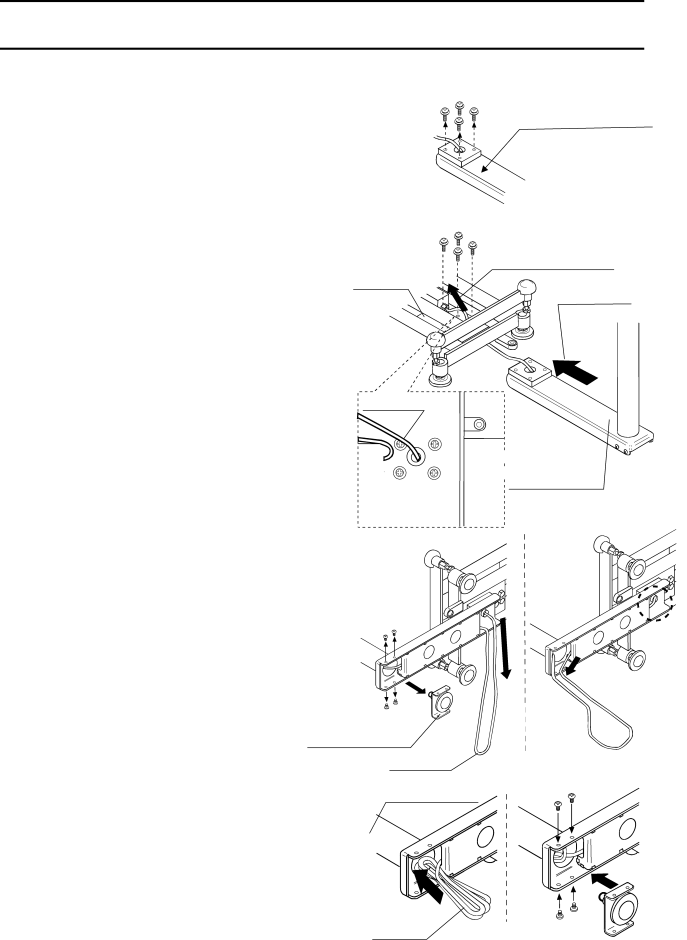
7.1.Attaching the display pole to the base

SW-M / L series with a display pole

2

Lower part of

1.

Remove the weighing pan from the


the display pole


base.


2.

Remove the 4 screws from the lower


part of the display pole.


3.

Insert the display pole under the base

4

3. Pull out the cable


while pulling out the cable into the base


and align the cable opening positions of

Base

3. Insert


the pole and the base. (See “3” in the


illustration.)

‰ Do not pull the cable forcibly. Take care not to pinch the cable between the pole and the base.

4. Align the screw holes of the pole and


Cable

the base. Using the 4 screws removed


at step 2 to secure the display pole to


the base firmly.


Base, seen


from above


Lower part of the display pole

5. Lay the base on its side.


Remove the 4 screws (“5” in the illustration)


and remove the pole support foot.


6. Pull the excess cable out of the base.

6

(See “6” in the illustration.)

5

‰ Take care not to damage the cable.


And make sure the cable has no


7

slack.


7. Pull the cable out to the pole side.

5


(See “7” in the illustration.)

Pole support foot


8.

Put the bundle of cable back into the

Cable


9


display pole. (See “8” in the illustration.)

Display pole

9.

Using the 4 screws removed at step 5,


secure the pole support foot to the


display pole.


10. Return the base to the upright position and

8


place the weighing pan on the base.

Bundle

9


10

Image 12
Contents SW Series Page Contents Maintenance SpecificationsOptions Gravity Acceleration MAPCompliance Compliance with FCC rulesClassification of protection provided by enclosures Features IntroductionPrecautions Installing the scaleCleaning the scale Operating the scaleUnpacking Description of Each Part Display rear sideDisplay and symbols SymbolsSymbol Description DisplaySwitches Setting UP Attaching the display pole to the baseSW-M / L series with a display pole Installing the scale Turning the power on and OFF Basic OperationBat oo ON/OFFIndicator will not turn on Selecting a weighing unitBasic weighing operation During the Tare operationWeight display resolution Counting Mode PrintFive-level comparator mode ComparatorFormula to compare LoloThree-level comparator mode Five-level comparator mode Three-level comparator mode Entering the comparator valuesPrint Sample Tare Calibration Gravity acceleration correctionCalibration using a weight Units PrintRestoring the factory set values Setting the parameters FunctionsTare ON/OFF Function list Key Using the OP-02 SLA battery Installing the batteryOptions Charging the battery Installing OP-03 OP-03 RS-232C / Relay OutputOP-03 Specifications AsciiSolid sate relay ‰ Data example Command mode Stable positive data Page Installing OP-04 OP-04 RS-422OP-04 Specifications Example of connection RS-422 Stable data Maintenance Error codesSpecifications SpecificationsModel SW-6KS SW-15KS SW-15KM SW-30KM Model SW-60KM SW-60KLExternal dimensions SW-60KL / SW-150KL with a display pole Gravity Acceleration MAP Values of gravity at various locationsWorld map