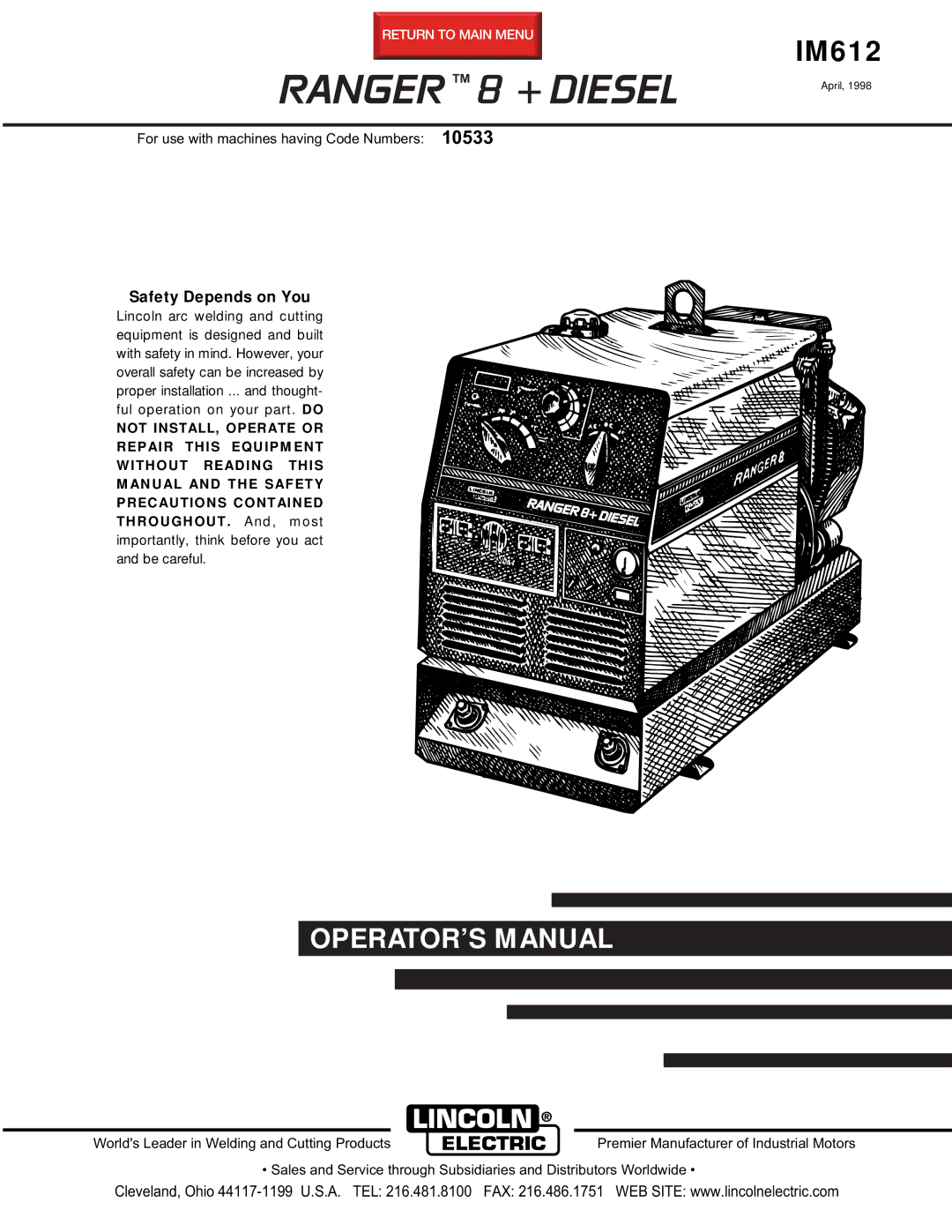
Lincoln Electric IM612 manual Installation, Technical Specifications Ranger 8+ Diesel K1632-1

Page 9

A-1

INSTALLATION

A-1

TECHNICAL SPECIFICATIONS - RANGER 8+ DIESEL (K1632-1)
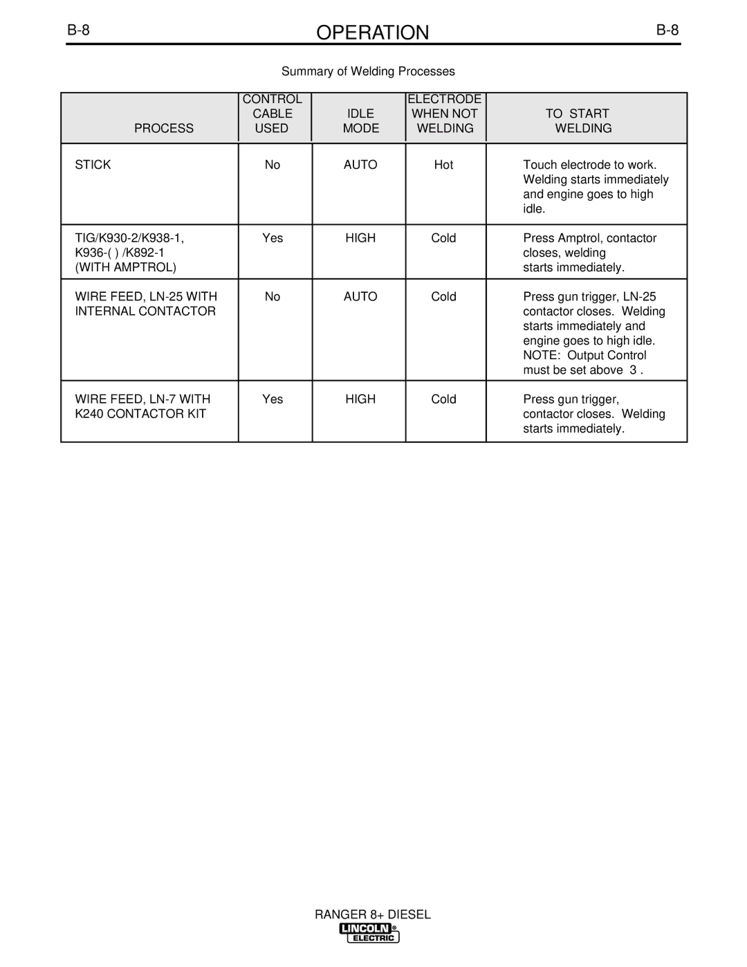


INPUT - DIESEL ENGINE


Make/Model

Description

Speed (RPM)


Displacement

Starting

Capacities


System


Ruggerini

2 cylinder

High Idle 3700


51.9 cu. in

12VDC battery

Fuel: 9.0 gal.

RD 201

4 Cycle

Low Idle 2200


(851 cc)


34.0 L

Diesel Engine

Air Cooled Diesel

Full Load 3500


w/Direct Injection


Horsepower


Oil: 3.2 Qts.


Diecast Aluminum


3.0 L


Crankcase


18.4 HP @


3600 RPM


RATED OUTPUT - WELDER

Welding Output

Volts at Rated Amps

Duty Cycle

Max. OCV @ 3700 RPM

DC Constant Current 225 amps

25 volts

100%


AC Constant Current 250 amps

25 volts

100%

80 volts RMS

DC Constant Voltage 200 amps

20 volts

100%


OUTPUT - GENERATOR

Auxiliary Power 1

9,000 Watts, 60 Hz

80 Amps @ 115 Volts / 40 Amps @ 230 Volts

100 % Duty Cycle

PHYSICAL DIMENSIONS

HEIGHT

WIDTH

DEPTH

WEIGHT

30.75 in.

19.09 in.

48.12 in.

695 lbs.

781.1 mm

484.9 mm

1222.2 mm

315 Kg.


1.Output rating in watts is equivalent to volt-amperes at unity power factor. Output voltage is within ± 10% at all loads up to rated capacity. When welding, available auxiliary power will be reduced.

RANGER 8+ DIESEL
Image 9
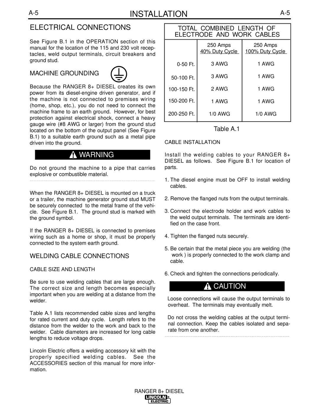
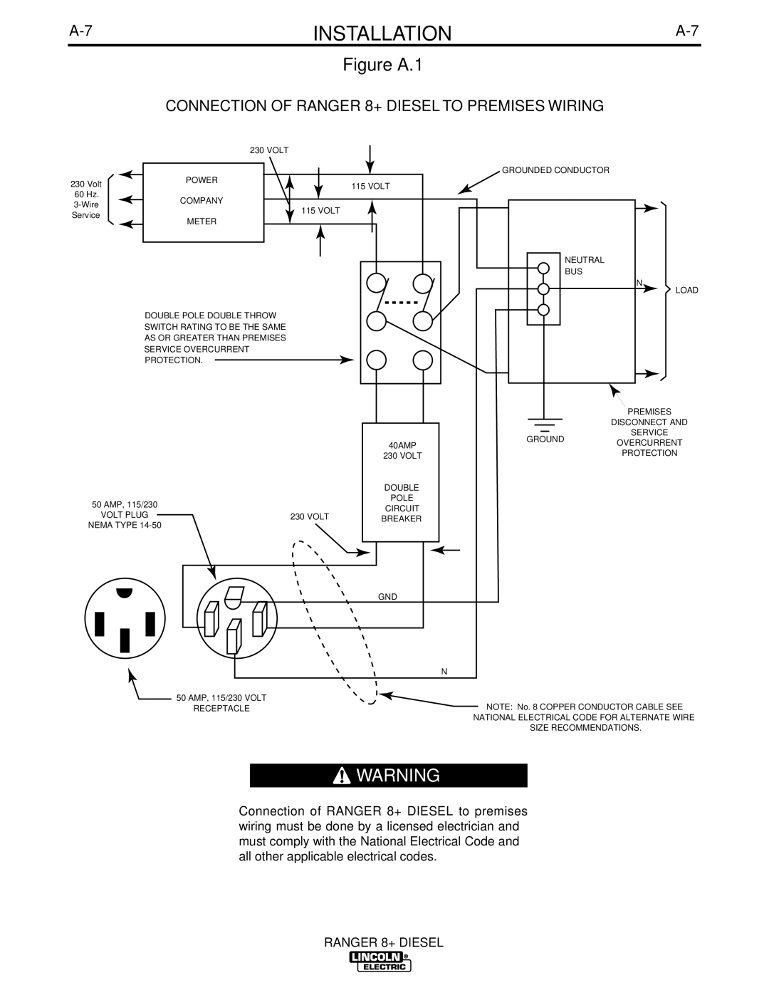
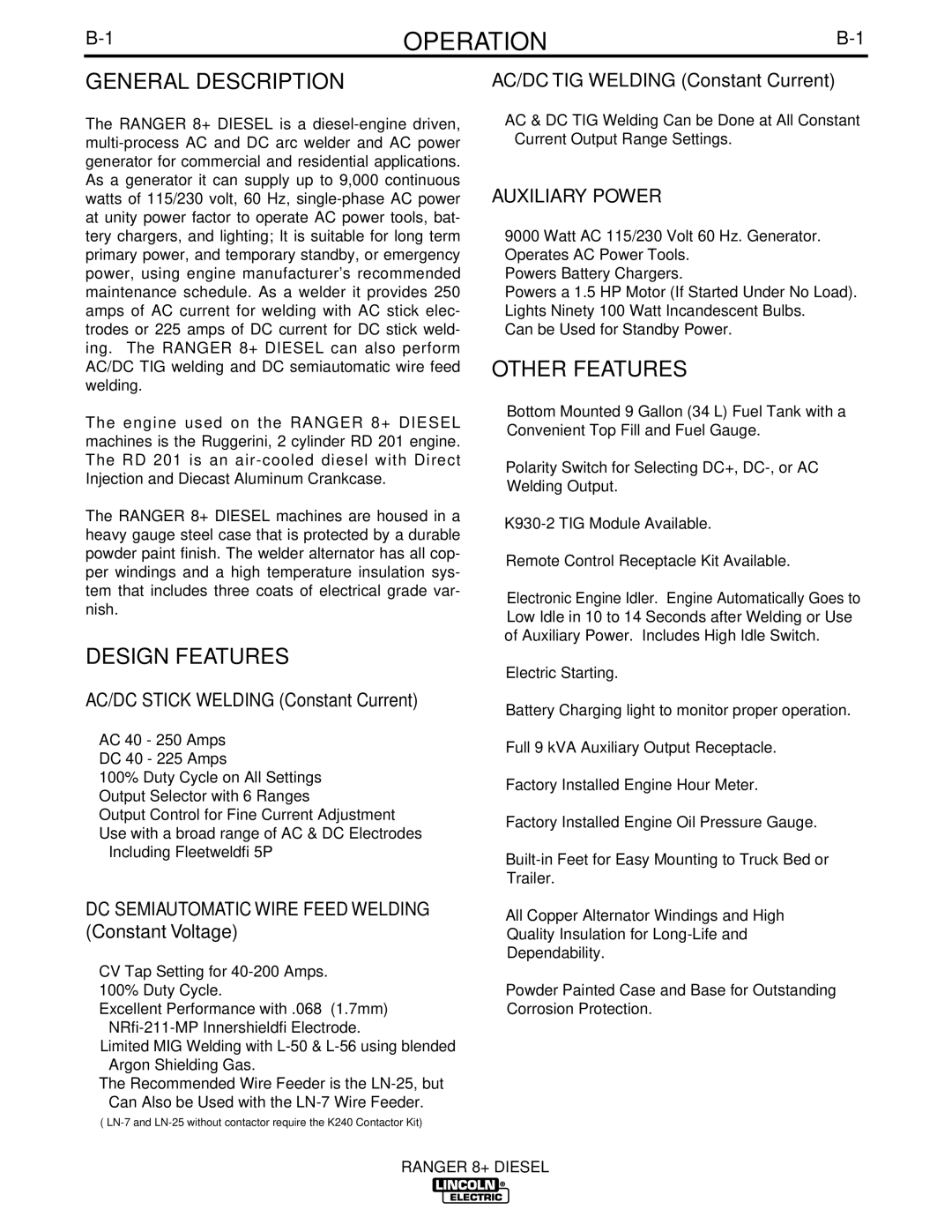
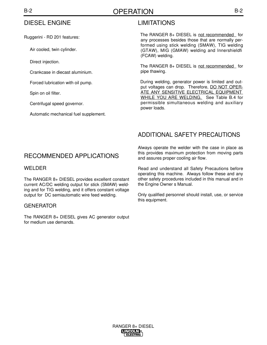
Contents Ranger 8 + Diesel California Proposition 65 Warnings SafetyElectric Shock can kill Cylinder may explode if damaged Sûreté Pour Soudage a L’Arc Précautions DE SûretéThank You Engine ServiceTable of Contents Vii Technical Specifications Ranger 8+ Diesel K1632-1 InstallationInstallation Instructions Additional Safety Precautions PRE-OPERATION Engine ServiceLifting OILBattery Connections FuelSpark Arrester Total Combined Length of Electrode and Work Cables Electrical ConnectionsMachine Grounding Welding Cable ConnectionsAuxiliary Power RECEPTACLES, PLUGS, and HAND-HELD Equipment Premises WiringCircuit Breakers Figure A.1 Connection of Ranger 8+ Diesel to Premises WiringOther Features Design FeaturesAuxiliary Power OperationDiesel Engine Additional Safety PrecautionsLimitations Recommended ApplicationsFigure B.1 Output Panel Controls Machine Controls Controls and SettingsOperation Before Starting the Engine Engine OperationStarting the Engine Stopping the EngineBREAK-IN Period Table B.1 Typical Ranger 8+ Diesel Fuel ConsumptionWelding Operation Welding Process Wire Feed Welding Processes Constant VoltageStick Constant Current Welding TIG Constant Current WeldingSummary of Welding Processes Auxiliary Power Simultaneous Welding and Power LoadsTable B.4 Figure B.3 115V Duplex Receptacles 115/230 Volt Dual Voltage ReceptacleAccessories General Options AccessoriesTIG Welding Options Accessories Semiautomatic Fcaw and MIG Welding Options / Acces Sories Connection of Ranger 8+ Diesel to LN-7 & K240 Contactor KIT Accessories Connection DiagramsMaintenance Safety PrecautionsRoutine Maintenance Battery Engine AdjustmentsEngine Maintenance Components Slip RingsHOW to USE Troubleshooting Guide TroubleshootingTroubleshooting Engine will not go to high idle Poor work lead connection to Troubleshooting Diagrams Maximum Overall Dimensions Ranger 8+ How To Read Shop Drawings Precaucion Warnung