Woodstock W1747 owner manual Extension Wings, Extension wing fasteners Leveling controls

Page 15

W1747 20" Planer

Extension Wings

Extension wings are heavy and could cause per- sonal injury if dropped during installation. Have an assistant hold the table while you fasten it to the planer.

To attach the table extension wings, do these steps:

1.With the help of an assistant, attach the table extension wings to the planer table (Figure 4) with the M8-1.25 x 25 hex bolts. Finger tighten the bolts for now.

2.Install the M8-1.25 x 20 set screws (Figure 4) in the holes in the bottom of the wings.

3.Check table-to-extension wing alignment (Figure 5) with a straightedge and adjust the leveling set screws until the table and wings are flush.

4.Tighten the hex bolts.
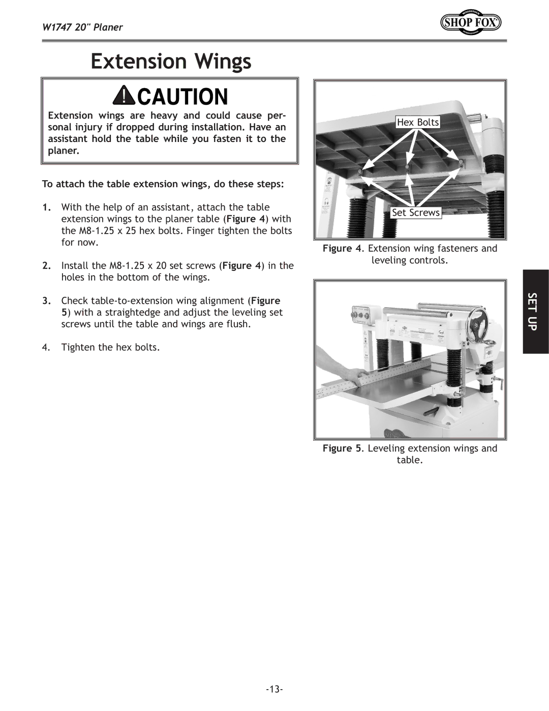
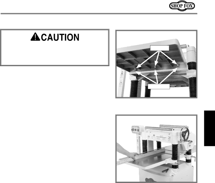
Hex Bolts

Set Screws

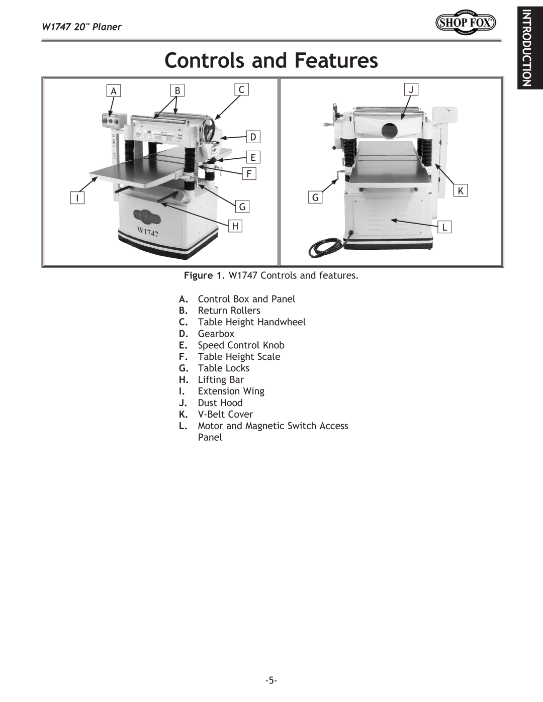
Figure 4. Extension wing fasteners and

leveling controls.

SET UP

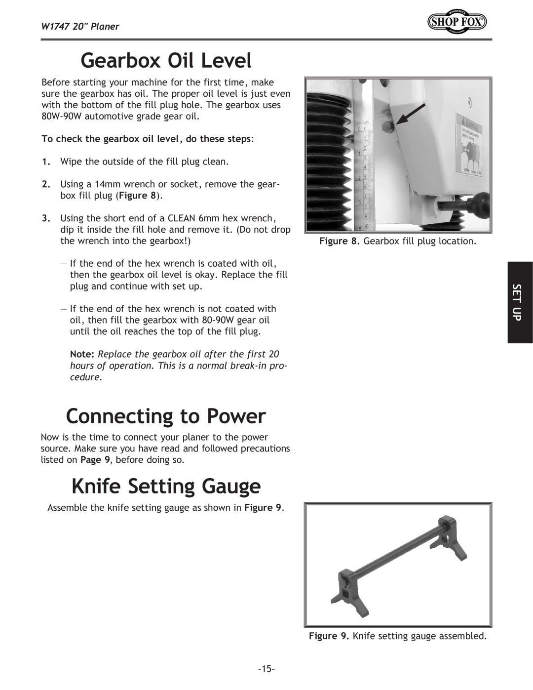
Figure 5. Leveling extension wings and

table.

-13-

Image 15
Contents Planer Page Contents Service Woodstock Technical Support IntroductionSpecifications Controls and Features Standard Safety Instructions SafetyAlways Lock Mobile Bases if Used Before Operating Machinery Additional Safety Instructions for Planers Grounding Electrical220V Operation Extension Cords Inventory SET UP Items Needed for Set Up UnpackingMachine Placement Lifting PlanerHardware and Tools These items are coated and must be cleaned Cleaning MachineExtension wing fasteners Leveling controls Extension WingsTo install the handwheel, do these steps HandwheelDust Hood To check the gearbox oil level, do these steps Connecting to PowerKnife Setting Gauge Gearbox Oil LevelTo perform a test run, do these steps Recommended AdjustmentsTest Run Tighten V-BeltsBasic steps of operating the planer are as follows OperationsGeneral Basic OperationOperation Tips Feed control knob positions Feed SpeedAdjustment Height Range 002-0.020 To adjust the bed rollers, do these stepsBed Rollers Planer Accessories AccessoriesOFF Maintenance CleaningMaintenance Schedule Belts To adjust/replace the V-belts, do these stepsLubrication Service Inspecting KnivesTo inspect the knives, do these steps To set the knives, do these steps Setting/Replacing KnivesChain Tension To adjust the chain tension, do these stepsMaximum Allowable Tolerances Table ParallelismTable micro-adjustment screws To adjust the table parallelism, do these stepsDistance Below Knife Edge at *BDC Rollers, Chip Breaker Pressure Bar Heights27, 28, Roller height adjustmentService Spring Tension To adjust roller spring tension, do these stepsTo calibrate the scale, do these steps Chip Deflector Gap SettingTo adjust the deflector position, do these steps Scale CalibrationAnti-kickback fingers Anti-Kickback FingersChecking belt alignment Pulley AlignmentW1747 motor junction box W1747 Electrical ComponentsW1747 Wiring Diagram Moving parts have come to a complete stop TroubleshootingCutting Headstock Assembly Parts Breakdown PART# Description Headstock Assembly Parts ListXPN09M Table, Base, and Columns Parts Breakdown Table, Base, and Columns Parts List Stand/Motor Assembly Parts Breakdown Stand/Motor Assembly Parts List Parts Warranty Comments Warranty RegistrationBOX BELLINGHAM, WA