Miller Electric H-10, MW 140 Plus warranty Process/Polarity Table, Changing Polarity

Page 17

5-3. Process/Polarity Table

Process

Polarity

Cable Connections


Cable To Gun

Cable To Work


GMAW − Solid wire with shield-

DCEP − Reverse polarity

Connect to positive (+) out-

Connect to negative (−) output

ing gas


put terminal

terminal


FCAW − Self-shielding wire −

DCEN − Straight Polarity

Connect to negative (−)

Connect to positive (+) output

no shielding gas


output terminal

terminal


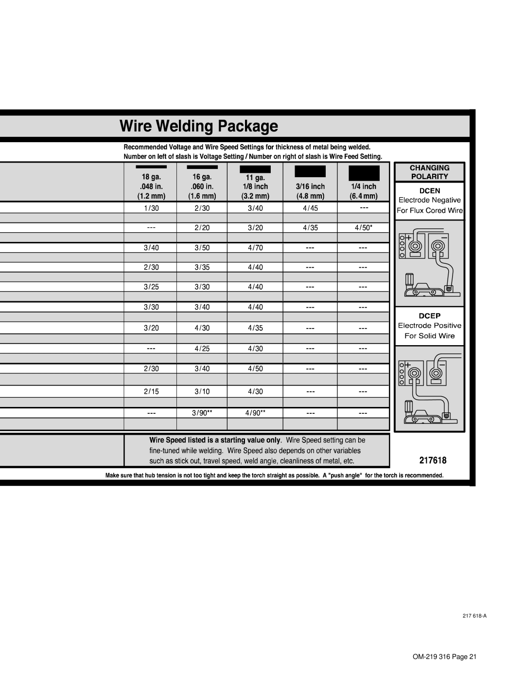
5-4. Changing Polarity

CHANGING

POLARITY

DCEN

Electrode negative for

flux cored wire

1

DCEP

Electrode positive for

solid wire

2

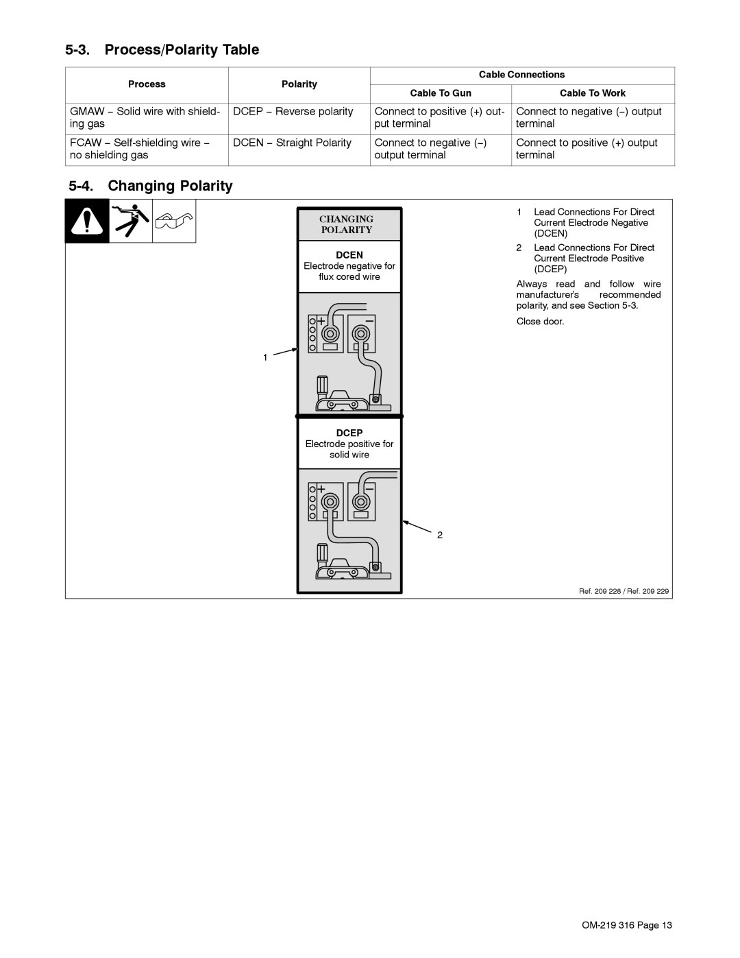
1Lead Connections For Direct Current Electrode Negative (DCEN)

2Lead Connections For Direct Current Electrode Positive (DCEP)

Always read and follow wire manufacturer’s recommended polarity, and see Section
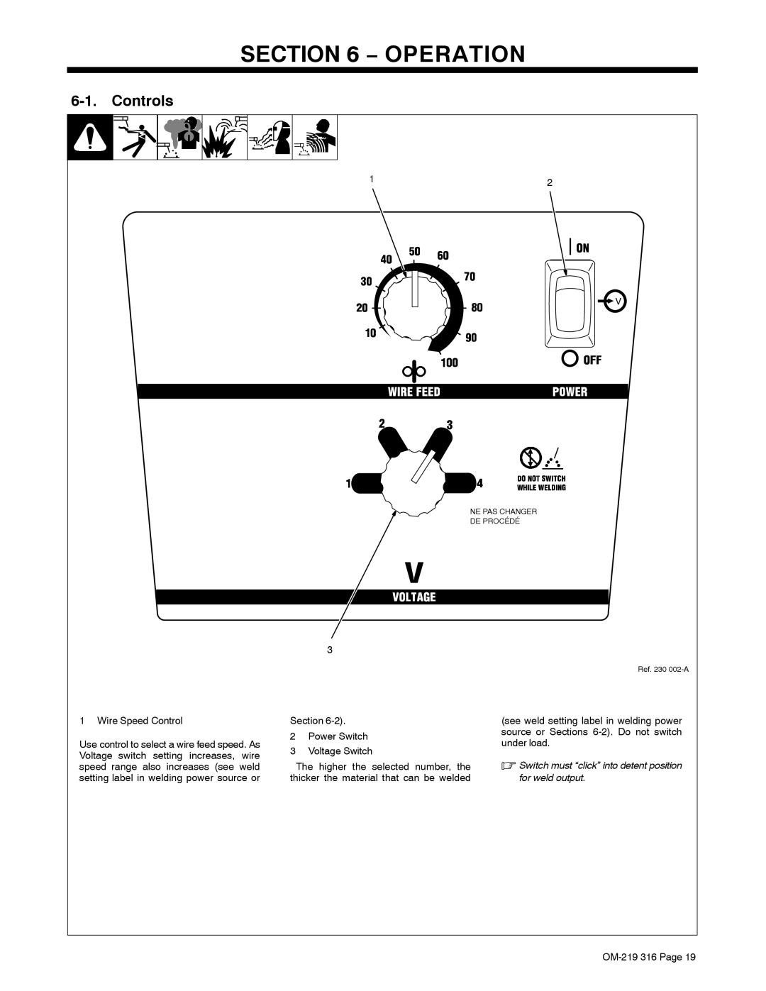
 5-3.

Close door.

Ref. 209 228 / Ref. 209 229

OM-219 316 Page 13

Image 17
Contents Processes OM-219 316C→Description 2006−10Page Table of Contents − Parts List Marks a special safety message Symbol UsageArc Welding Hazards Electric Shock can killWelding can cause fire or explosion ARC Rays can burn eyes and skinFlying Metal can injure eyes Buildup of GAS can injure or killCalifornia Proposition 65 Warnings About Pacemakers Principal Safety StandardsEMF Information Indique un message de sécurité particulier UNE Décharge Électrique peut entraîner la mortLES Fumées ET LES GAZ peuvent être dangereux Incendie ou une explosion LE Soudage peut provoquer unDES Particules Volantes peuvent blesser les yeux DES Pièces Chaudes peuvent provoquer des brûlures gravesLA Chute DE L’APPAREIL peut blesser Risque D’INCENDIE OU D’EXPLO’EMPLOI Excessif peut SUR DES Organes Mobiles peuvent provoquer des blessuresEn ce qui concerne les stimulateurs cardiaques Principales normes de sécuritéSymbols And Definitions − SpecificationsSpecifications − DefinitionsDuty Cycle And Overheating WarrantyOutput Duty Cycle % Exceeding duty cycle canAmperage Volt-Ampere CurvesInstalling Welding Gun − InstallationIncorrect CorrectChanging Polarity Process/Polarity TableCO 2 gas regulator/flowmeter Installing Gas SupplyDo not move or operate unit where it could tip Selecting a Location And Connecting Input PowerInstalling 8 in 203 mm Wire Spool Installing Wire Spool And Adjusting Hub TensionFlux Nozzle Installing Contact Tip And NozzleHold wire tightly to keep it from unraveling Threading Welding WireControls − OperationWeld Parameter Chart 217 618-A Routine Maintenance − Maintenance &TROUBLESHOOTINGOverload Protection Drive Motor ProtectionReplacing Gun Contact Tip Changing Drive Roll Or Wire Inlet GuideTurn Off power before replacing contact tip To Reassemble Gun Cleaning Or Replacing Gun LinerDisconnect gun from unit Replacing Switch And/Or Head Tube Does not run Troubleshooting TableTrouble Remedy Circuit Diagram − Electrical DiagramTypical MIG Process Connections − MIG Welding Gmaw GuidelinesWire Size Amperage Range Typical MIG Process Control SettingsThickness to Amperage a Select VoltageHolding And Positioning Welding Gun Conditions That Affect Weld Bead Shape Gun Movement During Welding Poor Weld Bead CharacteristicsGood Weld Bead Characteristics Troubleshooting − Porosity Troubleshooting − Excessive SpatterTroubleshooting − Excessive Penetration Possible Causes Corrective ActionsTroubleshooting − Burn-Through Troubleshooting − Lack Of PenetrationTroubleshooting − Incomplete Fusion Troubleshooting − Distortion Troubleshooting − Waviness Of BeadWire does not feed Troubleshooting Guide For Semiautomatic Welding EquipmentCommon MIG Shielding Gases ApplicationWelding arc not stable Wire slipping in drive rolls Main Assembly − Parts ListDia Part Description Quantity Dia Part Description Quantity Mkgs 195 H-10 GunOptions Optional Drive RollsWarranty Owner’s Record