Miller Electric MW 140 Plus, H-10 Cleaning Or Replacing Gun Liner, Disconnect gun from unit

Page 28

7-6. Cleaning Or Replacing Gun Liner

Tools Needed:

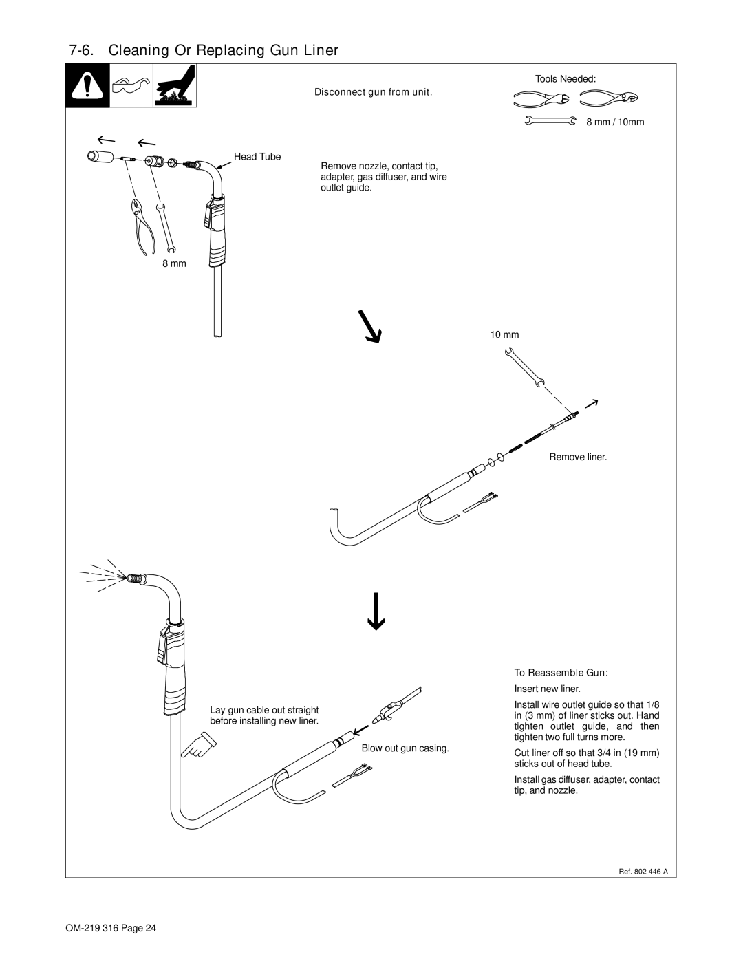
Y Disconnect gun from unit.

Head Tube

8 mm

8 mm / 10mm

Remove nozzle, contact tip, adapter, gas diffuser, and wire outlet guide.

10 mm

Remove liner.

Lay gun cable out straight before installing new liner.

To Reassemble Gun:

Insert new liner.

Install wire outlet guide so that 1/8 in (3 mm) of liner sticks out. Hand tighten outlet guide, and then tighten two full turns more.

Blow out gun casing.

Cut liner off so that 3/4 in (19 mm)


sticks out of head tube.

Install gas diffuser, adapter, contact tip, and nozzle.
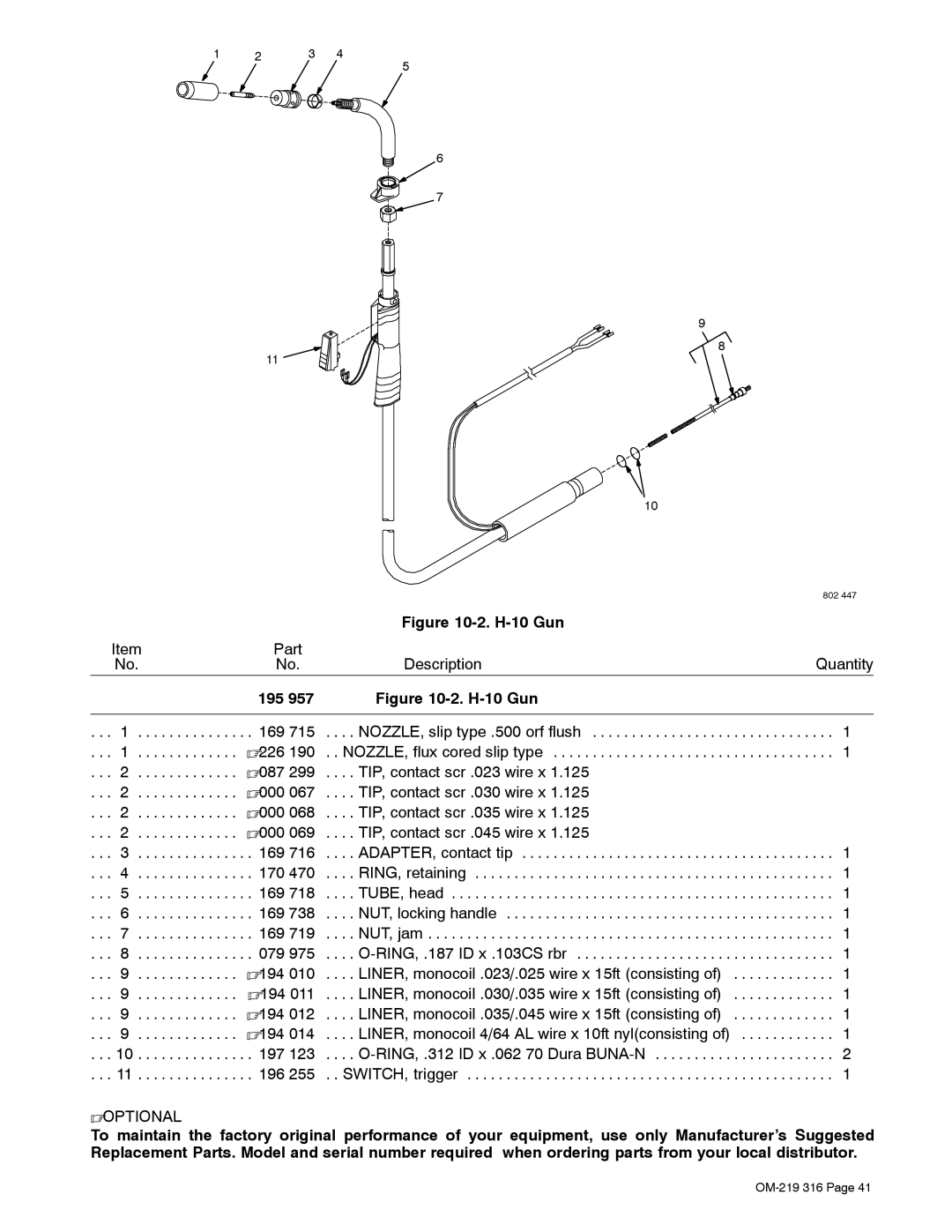
Ref. 802 446-A

OM-219 316 Page 24

Image 28
Contents OM-219 316C Processes→Description 2006−10Page Table of Contents − Parts List Symbol Usage Marks a special safety messageArc Welding Hazards Electric Shock can killARC Rays can burn eyes and skin Welding can cause fire or explosionFlying Metal can injure eyes Buildup of GAS can injure or killCalifornia Proposition 65 Warnings EMF Information Principal Safety StandardsAbout Pacemakers LES Fumées ET LES GAZ peuvent être dangereux UNE Décharge Électrique peut entraîner la mortIndique un message de sécurité particulier LE Soudage peut provoquer un Incendie ou une explosionDES Particules Volantes peuvent blesser les yeux DES Pièces Chaudes peuvent provoquer des brûlures gravesRisque D’INCENDIE OU D’EXPLO LA Chute DE L’APPAREIL peut blesser’EMPLOI Excessif peut SUR DES Organes Mobiles peuvent provoquer des blessuresPrincipales normes de sécurité En ce qui concerne les stimulateurs cardiaques− Specifications Symbols And DefinitionsSpecifications − DefinitionsWarranty Duty Cycle And OverheatingOutput Duty Cycle % Exceeding duty cycle canVolt-Ampere Curves Amperage− Installation Installing Welding GunIncorrect CorrectProcess/Polarity Table Changing PolarityInstalling Gas Supply CO 2 gas regulator/flowmeterSelecting a Location And Connecting Input Power Do not move or operate unit where it could tipInstalling Wire Spool And Adjusting Hub Tension Installing 8 in 203 mm Wire SpoolInstalling Contact Tip And Nozzle Flux NozzleThreading Welding Wire Hold wire tightly to keep it from unraveling− Operation ControlsWeld Parameter Chart 217 618-A − Maintenance &TROUBLESHOOTING Routine MaintenanceOverload Protection Drive Motor ProtectionTurn Off power before replacing contact tip Changing Drive Roll Or Wire Inlet GuideReplacing Gun Contact Tip Disconnect gun from unit Cleaning Or Replacing Gun LinerTo Reassemble Gun Replacing Switch And/Or Head Tube Trouble Remedy Troubleshooting TableDoes not run − Electrical Diagram Circuit Diagram− MIG Welding Gmaw Guidelines Typical MIG Process ConnectionsTypical MIG Process Control Settings Wire Size Amperage RangeThickness to Amperage a Select VoltageHolding And Positioning Welding Gun Conditions That Affect Weld Bead Shape Good Weld Bead Characteristics Poor Weld Bead CharacteristicsGun Movement During Welding Troubleshooting − Excessive Spatter Troubleshooting − PorosityTroubleshooting − Excessive Penetration Possible Causes Corrective ActionsTroubleshooting − Incomplete Fusion Troubleshooting − Lack Of PenetrationTroubleshooting − Burn-Through Troubleshooting − Waviness Of Bead Troubleshooting − DistortionTroubleshooting Guide For Semiautomatic Welding Equipment Wire does not feedCommon MIG Shielding Gases ApplicationWelding arc not stable Wire slipping in drive rolls − Parts List Main AssemblyDia Part Description Quantity Dia Part Description Quantity Mkgs H-10 Gun 195Optional Drive Rolls OptionsWarranty Owner’s Record