Miller Electric MW 140 Plus, H-10 warranty Holding And Positioning Welding Gun

Page 34

9-3. Holding And Positioning Welding Gun
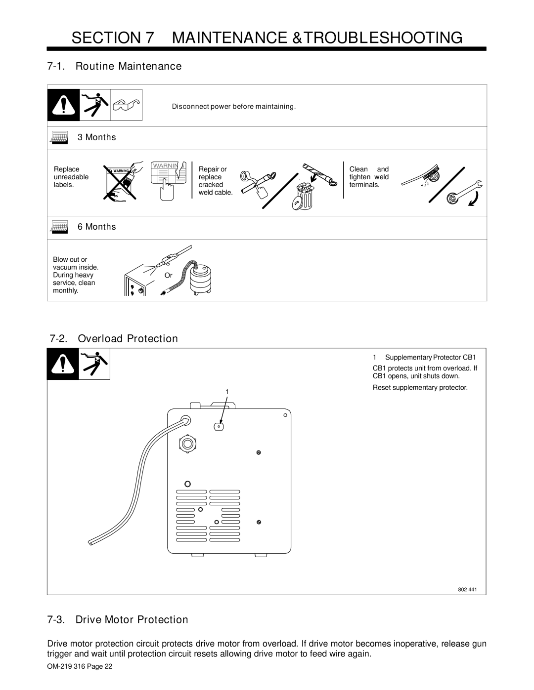
NOTE

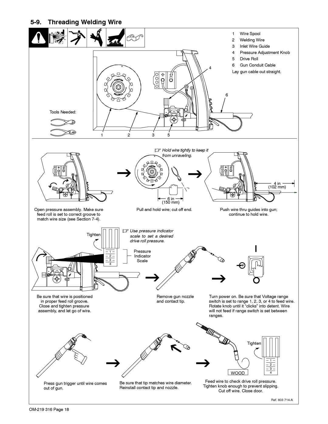
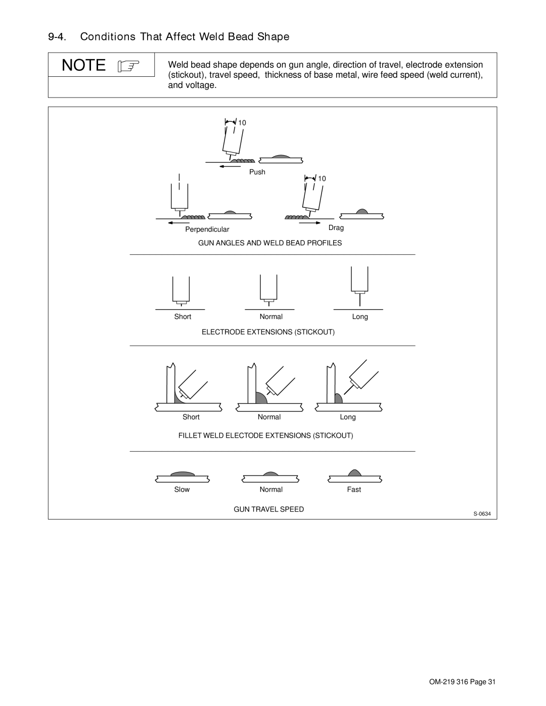
Welding wire is energized when gun trigger is pressed. Before lowering helmet and pressing trigger, be sure wire is no more than 1/2 in (13 mm) past end of nozzle, and tip of wire is positioned correctly on seam.


1


1

Hold Gun and Control Gun


Trigger


2

Workpiece


3

3

Work Clamp


2

4

Electrode Extension (Stickout)


1/4 to 1/2 in (6 To 13 mm)


5 Cradle Gun and Rest Hand on

5


Workpiece


4


0°-15°


90°

90°


End View of Work Angle

Side View of Gun Angle


GROOVE WELDS


45°

0°-15°


45°


End View of Work Angle

Side View of Gun Angle


FILLET WELDS


S-0421-A

OM-219 316 Page 30

Image 34
Contents →Description OM-219 316CProcesses 2006−10Page Table of Contents − Parts List Arc Welding Hazards Symbol UsageMarks a special safety message Electric Shock can killFlying Metal can injure eyes ARC Rays can burn eyes and skinWelding can cause fire or explosion Buildup of GAS can injure or killCalifornia Proposition 65 Warnings EMF Information Principal Safety StandardsAbout Pacemakers LES Fumées ET LES GAZ peuvent être dangereux UNE Décharge Électrique peut entraîner la mortIndique un message de sécurité particulier DES Particules Volantes peuvent blesser les yeux LE Soudage peut provoquer unIncendie ou une explosion DES Pièces Chaudes peuvent provoquer des brûlures graves’EMPLOI Excessif peut SUR Risque D’INCENDIE OU D’EXPLOLA Chute DE L’APPAREIL peut blesser DES Organes Mobiles peuvent provoquer des blessuresPrincipales normes de sécurité En ce qui concerne les stimulateurs cardiaquesSpecifications − SpecificationsSymbols And Definitions − DefinitionsOutput Duty Cycle % WarrantyDuty Cycle And Overheating Exceeding duty cycle canVolt-Ampere Curves AmperageIncorrect − InstallationInstalling Welding Gun CorrectProcess/Polarity Table Changing PolarityInstalling Gas Supply CO 2 gas regulator/flowmeterSelecting a Location And Connecting Input Power Do not move or operate unit where it could tipInstalling Wire Spool And Adjusting Hub Tension Installing 8 in 203 mm Wire SpoolInstalling Contact Tip And Nozzle Flux NozzleThreading Welding Wire Hold wire tightly to keep it from unraveling− Operation ControlsWeld Parameter Chart 217 618-A Overload Protection − Maintenance &TROUBLESHOOTINGRoutine Maintenance Drive Motor ProtectionTurn Off power before replacing contact tip Changing Drive Roll Or Wire Inlet GuideReplacing Gun Contact Tip Disconnect gun from unit Cleaning Or Replacing Gun LinerTo Reassemble Gun Replacing Switch And/Or Head Tube Trouble Remedy Troubleshooting TableDoes not run − Electrical Diagram Circuit Diagram− MIG Welding Gmaw Guidelines Typical MIG Process ConnectionsThickness to Amperage a Typical MIG Process Control SettingsWire Size Amperage Range Select VoltageHolding And Positioning Welding Gun Conditions That Affect Weld Bead Shape Good Weld Bead Characteristics Poor Weld Bead CharacteristicsGun Movement During Welding Troubleshooting − Excessive Penetration Troubleshooting − Excessive SpatterTroubleshooting − Porosity Possible Causes Corrective ActionsTroubleshooting − Incomplete Fusion Troubleshooting − Lack Of PenetrationTroubleshooting − Burn-Through Troubleshooting − Waviness Of Bead Troubleshooting − DistortionCommon MIG Shielding Gases Troubleshooting Guide For Semiautomatic Welding EquipmentWire does not feed ApplicationWelding arc not stable Wire slipping in drive rolls − Parts List Main AssemblyDia Part Description Quantity Dia Part Description Quantity Mkgs H-10 Gun 195Optional Drive Rolls OptionsWarranty Owner’s Record