|
|
| |||
|
|
|
| ||
|
|
|
| ||
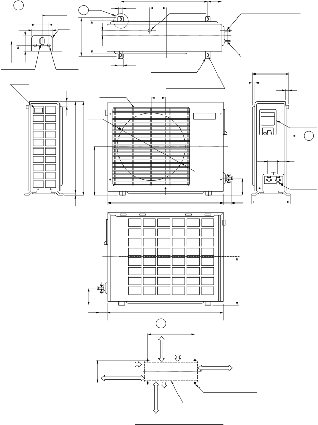
| A Detail Drawing | A | 36 | ||
|
|
| 600 |
| |
|
| 36 | R10 |
|
|
|
| 50 |
|
| |
|
|
| 230 | 216 | 30 |
230 | 216 | 25 |
|
| 50 |
ø11x14 Hole | ø6 Hole |
| |||
|
| ||||
60085
111
ø25 Drain hole
Gas side (flare ø9.52)
Liquid side (flare ø6.35)
Handle |
|
11 | Fan guard |
| |
| ø420 |
525 | 530 |
268
(For fixing the outdoor unit)
12
111(For anchor bolt
TOSHIBA
200
11
Electric parts cover
Z
54 62
5
|
|
| Access for |
|
| 89 | charging |
|
|
| |
770 | 59 |
| 250 |
89
230
268
59 | 770 |
|
| Z View |
|
or more | 600 |
|
Inlet port |
| |
45 |
| 600 or more |
Inlet port |
| |
|
| |
100 or more | Visible outline | (Minimum distance |
| of the product | of the wall) |
more | Outlet | ||
(For anchor bolt | |||
port | |||
or |
| Center | |
200 |
| ||
| port |
Mounting dimension of anchor bolt
– 7 –