Enviro Cara owner manual Do not interfere with the structural integrity of the walls

Page 26

Initial Installation

QUALIFIED INSTALLERS ONLY

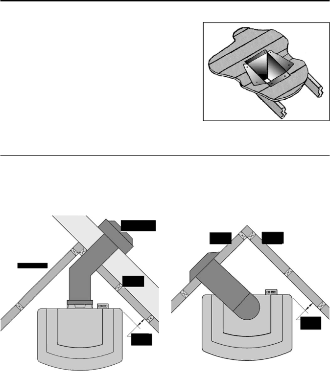
5.Using tin snips, cut the “Support Box” from the top corners down to the roof line, and fold the resulting flaps over the roof sheathing (Figure 42). Before nailing it in to the roof, run a bead of non-hardening mastic around the top edges of the “Support Box”, to make a seal between the box and the roof. Clean out any combustible material from the inside of the “Support Box”.

6.Complete the cathedral ceiling installation by following the same procedures outlined in Steps 4 through 9 for INITIAL

INSTALLATION - VERTICAL INSTALLATION.

Figure 42: Cathedral Ceiling Support Box

Installation.

CORNER INSTALLATIONS:

Do not interfere with the structural integrity of the walls.

For installations with a 36” (915 mm) snorkel refer to Figure 43 and INITIAL INSTALLATION - VENT CONFIGURATIONS AND RESTRICTOR SETTINGS. For other corner installations refer to Figure 44 and INITIAL INSTALLATION - VENT

CONFIGURATIONS AND RESTRICTOR SETTINGS.

Also refer to INITIAL INSTALLATION - CLEARANCES TO COMBUSTIBLES.


Figure 43: Corner installation rear vented with


Figure 44: Corner installation top vented.

snorkel.


26

Image 26
Contents Cara Safety Precautions GeneralTable of Contents Snorkel refer to ‘Converting Top Vented into Rear Vented’ Certified for installation from 0-4500 ft 0-1372 mCodes And Approvals Vented GAS Fireplace Heater Cara DV NG/LPGSpecifications Cara Exterior DimensionsFor Your Safety Read Before Operating Operating InstructionsCara Component Sound & Reason Maintenance And Service Pilot FlameNo substitute materials are allowed Check burner for proper operation Kit Parts List Conversion Kit InstallationOpen Flame When Testing for Leaks Initial Installation Qualified Installers onlyCathedral Ceiling Manufacturer Trade Name Nominal Sizes 4DSC Vent Termination Restrictions Top Flue Restrictor Installation 51mm at top, 11⁄2 38mm at sides, 11⁄2 38mm at bottom Wall Framing Hole forInstalling Horizontal Vent Termination Box up through the roof line. Galvanized Roof Pitch Minimum Height Feet Meters Follow installation steps 1 & 2 under Initial Do not interfere with the structural integrity of the walls Converting Top Vented into Rear Vented Installation for Top Vented Horizontal Termination Manifold Pressure Venturi SettingNatural Gas Propane Main Burner Min. Manifold PressureA. Installations Wire Size Max. LengthCanadian Installations Optional Blower Fan Installation Secondary Installation Log Placement of Rear Log ChunksLog Placement of Left Log Remove door to clean glass Addition the seven 7 small rocks. These can be To clean glass Trouble Shooting Problem Possible Cause SolutionParts List Reference Part Description NumberParts List Parts Diagram Warranty To the DealerWarranty Warranty Installation Data Sheet