Manitowoc Ice S manual Removing the Front Panels, Water Inlet Valve

Page 52

Maintenance

Section 4


Water Inlet Valve

The water inlet valve normally does not require removal for cleaning. Refer to Section 5 for a list of causes for “No Water Entering Water Trough” or “Water Overflows Water Trough.

1.When the ice machine is off, the water inlet valve must completely stop water flow into the machine.

2.When the ice machine is on, the water inlet valve must allow the proper water flow through it. Set the toggle switch to ON. Watch for water flow into the ice machine. If the water flow is slow or only trickles into the ice machine, refer to Section 5.

Follow the procedure below to remove the water inlet valve.

!Warning

Disconnect the electric power to the ice machine and dispenser at the electric service switch box and turn off the water supply before proceeding.

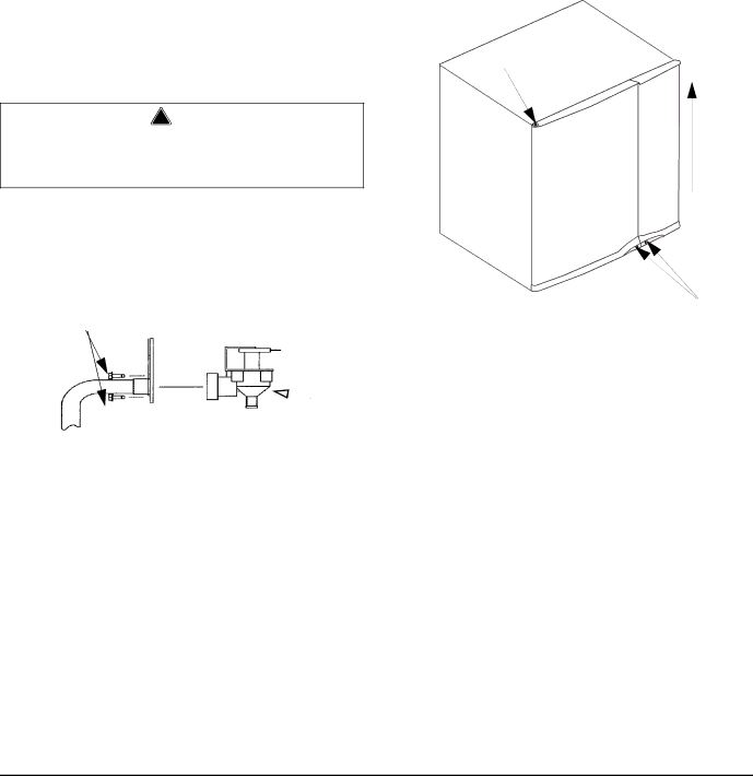
1.Remove the 1/4” hex head screws.

2.Remove, clean, and install the filter screen.

FILTER

ACCESS

SCREWS

WATER

INLET

VALVE

SV1622

Removing the Front Panels

NOTE: The front panels do not normally have to be removed. If needed perform the following procedure.

1.Loosen screws. Do not remove they are retained by o-rings to prevent loss.

2.30 Inch and 48 Inch Models Only: To remove right front door lift up and remove (22 inch machines have a single door, proceed to step 3).

5

3

2

Door Removal

3.Open left front door to 45 degrees.

4.Support with left hand, depress top pin, tilt top of door forward and lift out of bottom pin to remove.

4-12

Part Number 80-1620-3

Image 52
Contents Model Ice Machines Read These Before Proceeding Personal Injury PotentialPage Manitowoc ICE, INC Table of Contents Section Ice Machine Operation Table of ContentsSection Table of Contents Maintenance Section Before Calling For ServiceTable of Contents How to Read a Model Number Model NumbersIce Cube Sizes Self-Contained Remote Air-CooledGeneral Information Section Accessories Section General Information Model/Serial Number Location Model/Serial Number LocationWarranty Coverage Ice Machine Dimensions Ice Machine Dimension W Dimension D Dimension HGeneral S320/S420 AIR and WATER-COOLED ICE MachinesS600 AIR and WATER-COOLED ICE Machines Installation Instructions SectionS600 Remote ICE Machines Width, Depth, and Height Dimensions Electrical and AuCS DimensionsIce Storage Bin Dimensions Bin Model Dimension a Dimension BS500/S850/S1000 Remote ICE Machines Inch 76 CM ICE Storage Bins Inch 56 CM ICE Storage BinsS1400/S1600/S1800 AIR and WATER-COOLED ICE Machines S1400 / S1800 Remote ICE MachinesInch 130 CM ICE Storage Bins B970Section Installation Instructions Location of Ice Machine Ice Machine Heat of RejectionLeveling Leg and Foot Air-Cooled BaffleAir Baffle Section Installation Instructions Electrical Service VoltageFuse/Circuit Breaker Minimum Circuit AmpacityMaximum Breaker Size & Minimum Circuit Amperage Chart For United Kingdom Only Self Contained ICE Machine 115/1/60 or 208-230/1/60Self Contained ICE Machine 208-230/3/60 Self Contained ICE Machine 230/1/50Single Cooling Tower Applications Water-Cooled Models Water SupplyWater Inlet Lines Drain ConnectionsTypical Water Supply Drain Installation Water Supply and Drain Line SIZING/CONNECTIONSCondenser Bin DrainAir Temperature Around the Condenser Remote ICE Machines Refrigerant ChargeIce Machine Remote Single Line Set Circuit Condenser Line Set Discharge Line Liquid LineGuidelines for Routing Line Sets Routing Line SetsCalculating Remote Condenser Installation Distances Connecting a Line SET Remote Receiver Service ValveBackseating the Receiver Service Valve Lengthening or Reducing Line SET LengthsWarranty Internal Condenser VolumeHead Pressure Control Valve FAN MotorNON-MANITOWOC MULTI-CIRCUIT Condenser Sizing Chart Typical Single Circuit Remote Condenser InstallationSection Installation Instructions Installation Check List Additional Checks for Remote ModelsAuCS Automatic Cleaning System Section Ice Machine Operation Component IdentificationIce Machine Operation Section Sequence Of Operation Initial START-UP or START-UP After Automatic SHUT-OFFSafety Timers Harvest Sequence 5. Water PurgeHarvest Automatic SHUT-OFF 7. Automatic Shut-OffIce Machine Operation Section Operational Checks Water LevelICE Thickness Check Ice Thickness CheckWater Purge Adjustment Harvest Sequence Water PurgeIce Machine Operation Section Section Maintenance Exterior CleaningCleaning the Condenser Ice Machine InspectionMaintenance Section Water-Cooled Condenser Water Regulating ValveAlphaSan Straighten Bent Condenser FinsSection Maintenance Guardianf Guardianf Location GUARDIANf Sachet Replacement FrequencySachet INSTALLATION/REPLACEMENT Procedure Clean UP Procedure for Damaged Sachet PacketMaintenance Section Interior Cleaning and Sanitizing Cleaning ProcedureModel Amount of Cleaner StepSolution Type Water Mixed With Sanitizing ProcedureModel Amount of Sanitizer Removal of Parts for CLEANING/SANITIZING Water Curtain Removal Ice Thickness Probe Water CurtainIce Thickness Probe Removal Water Trough Water Distribution TubeWater Distribution Tube Removal Water Pump Water Level ProbeWater Pump Removal Dump Valve Disassembly Water Dump ValveEvaporator Tray Removal Drain Line Check ValveRemoving the Front Panels Water Inlet ValveSection Maintenance Removal from Service/Winterization SELF-CONTAINED AIR-COOLED ICE MachinesWATER-COOLED ICE Machines Remote ICE MachinesThis page Intentionally Left Blank Checklist Problem Possible Cause To CorrectBefore Calling For Service Section Safety Limit Feature