Bertazzoni X)486GPIRX, X)486GPIRVI, (A manual Installing the Legs, Installing the Worktop Frontguard

Page 10

INSTALLING THE LEGS

Bertazzoni ranges must be used only with the legs properly installed.

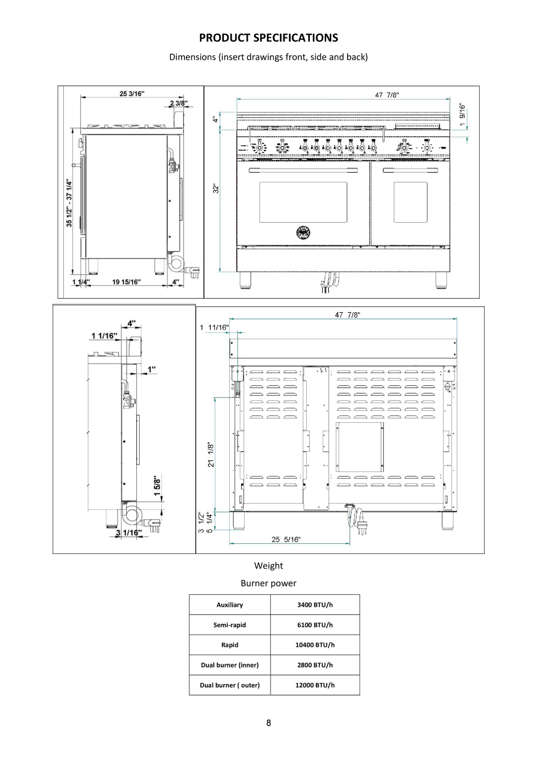
Four height‐adjustable legs are shipped with the range in the polystyrene container situated over the appliance.

Before installing the legs, position the appliance near its final location as the legs are not suitable for moving the appliance over long distances.

After unpacking the range, raise it enough to insert the legs in the appropriate receptacles situated on the lower part of the appliance. Lower the range gently to keep any undue strain from legs and mounting hardware. If possible use a pallet or lift jack instead of tilting the unit.

Adjust leg height to the desired level by twisting the inside portion of the leg assembly until the proper height is reached. Check with a level that the cooktop is perfectly level.

INSTALLING THE WORKTOP

FRONTGUARD

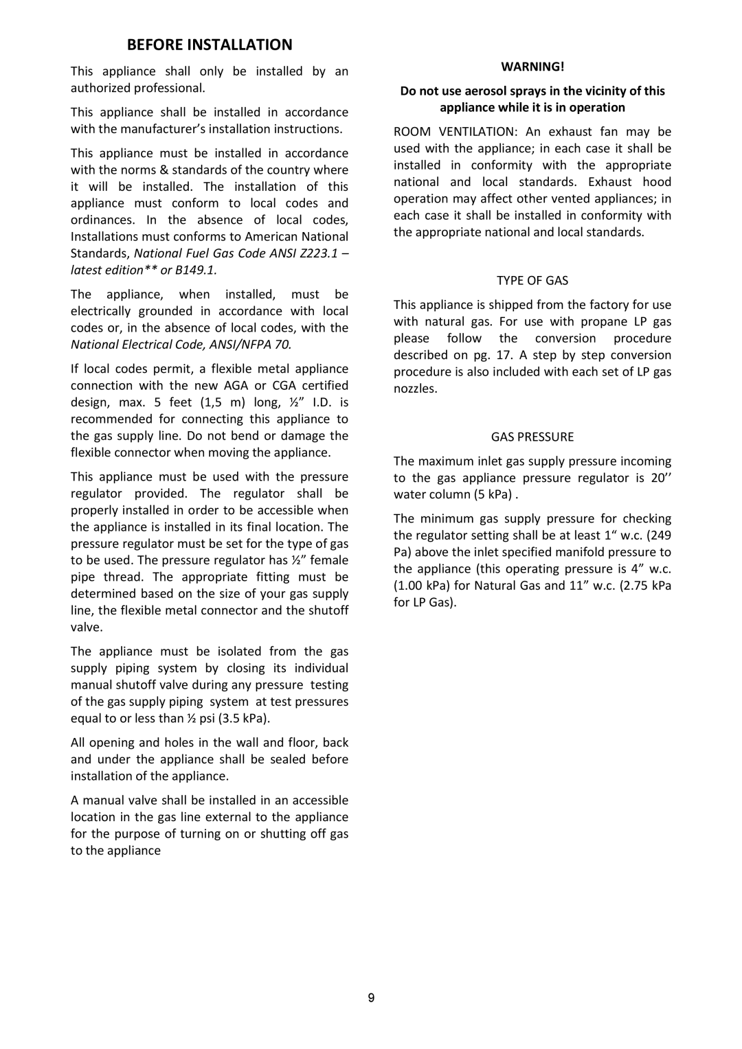
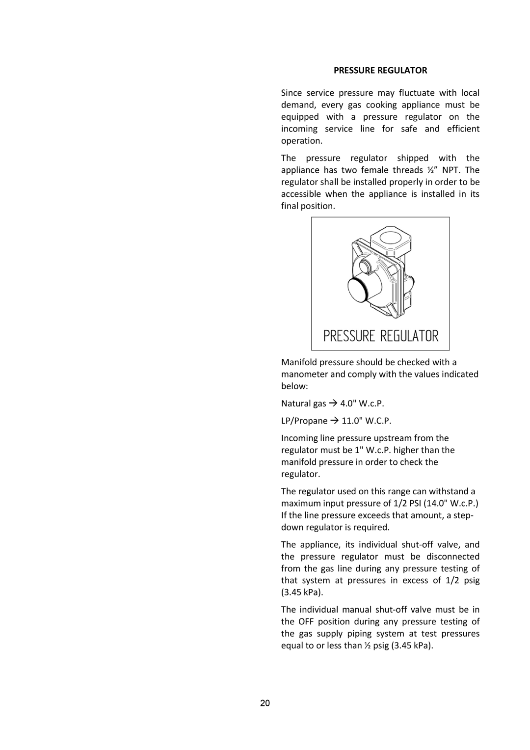
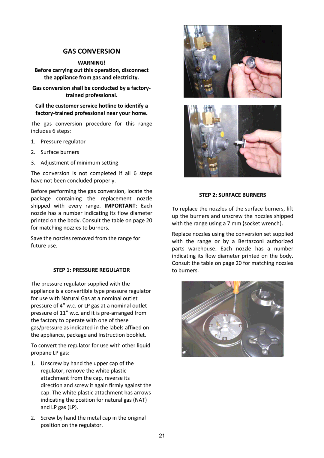
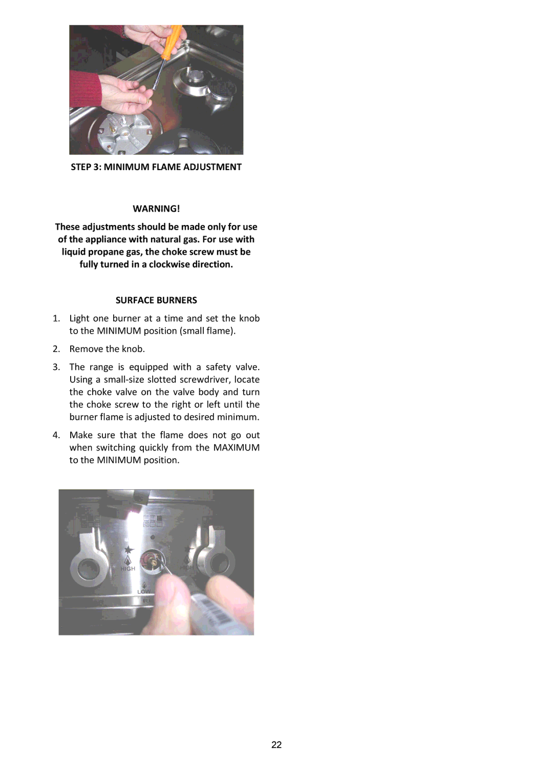
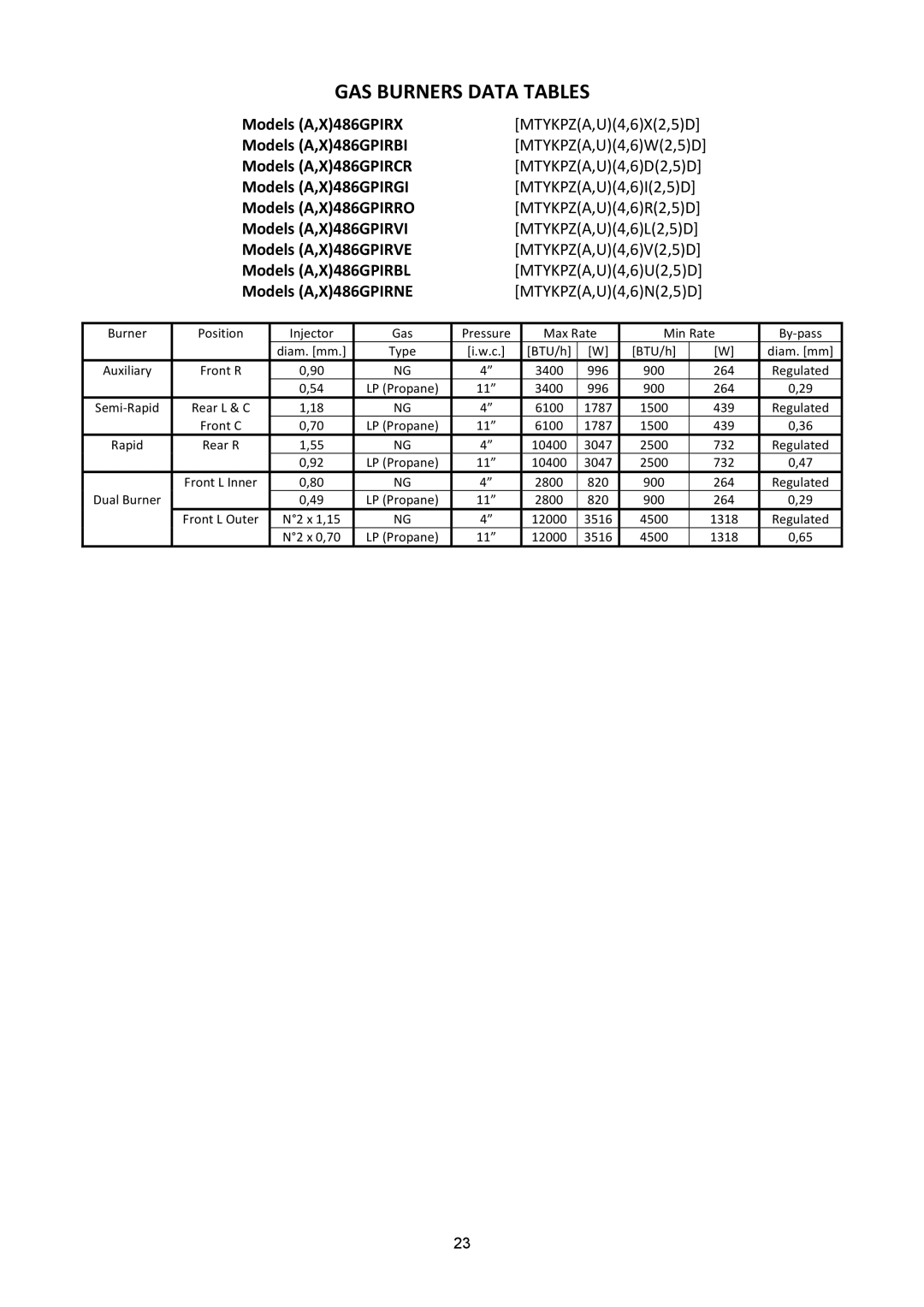
To increase the clearance between the front edge of the worktop and the burners it is possible to install the worktop front guard shipped with the appliance.

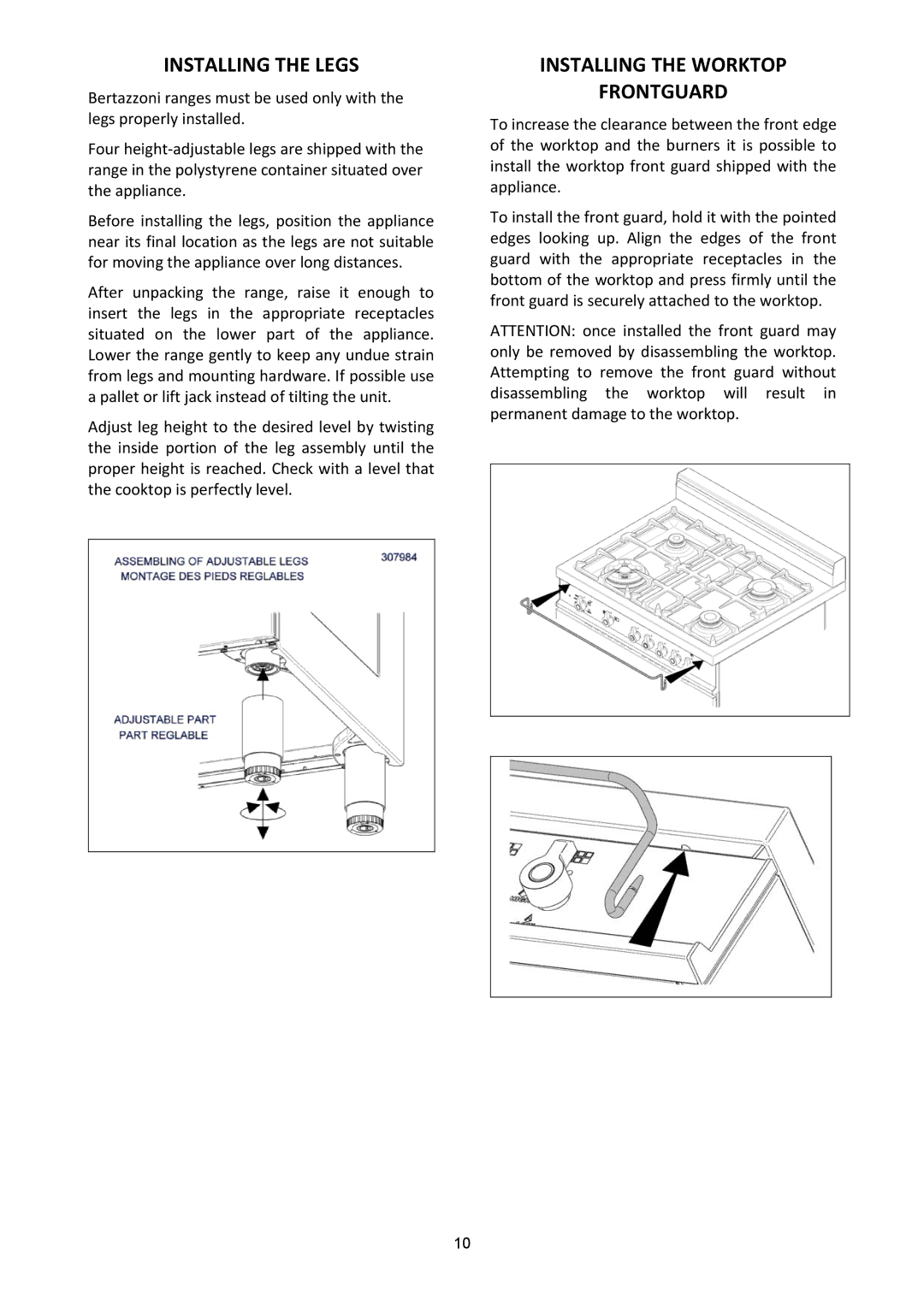
To install the front guard, hold it with the pointed edges looking up. Align the edges of the front guard with the appropriate receptacles in the bottom of the worktop and press firmly until the front guard is securely attached to the worktop.

ATTENTION: once installed the front guard may only be removed by disassembling the worktop. Attempting to remove the front guard without disassembling the worktop will result in permanent damage to the worktop.

10
Image 10
Contents Models A,X486GPIRX From the desk of the President Table of Contents Page Customer Service Warranty and ServiceReplacement Parts Important Safety Information What to do if YOU Smell GASPage Product Specifications Auxiliary 3400 BTU/hBefore Installation Type of GASInstalling the Legs Installing the Worktop FrontguardInstalling the Backguard Electrical Installation RequirementsGAS Installation Adjacent to Kitchen Cabinets Exhaust Hood InstallationElectrical Connection Left OvenPage Electrical Shock Hazard Electrical GroundingLocation of Appliance Plates Wiring Diagram Right Oven + Griddle Manual SHUT‐OFF Valve Do not USE AN Open Flame When Checking For LeaksGAS Connection Flexible ConnectionsPressure Regulator GAS Conversion Surface BurnersMinimum Flame Adjustment GAS Burners Data Tables Installation Checklist Final PreparationRoom Ventilation Surface Cooking SymbolsSurface Burner Layout X486GPIRX,BI,CR,GI,RO,VI,VE,BL,NEElectric Ignition Surface Burner Operation Thermocouple Safety ValveManual Ignition Tips for Using Pans Correctly Using the Electric GriddleSeasoning the Griddle Oven Cooking Left Oven Griddle cooking recommendationsOven Racks Oven Function SelectorUsing the Oven Bake ConvectionBAKE/CONVECTION/TURBO Rack PositionsProofing Slow Cooking and LOW Temperature Uses of the OvenWarming Baking RecommendationsDehydrate FruitBroil / Convection Broil Tips for BroilingBroiling and Roasting Recommendations BeefElectric Oven Maintaining Your Range Door LockCleaning Your Range Do not clean the range when hotTroubleshooting Guide Oven Problem Possible Causes AND/OR RemedyLocation of Appliance Tags Important Appliance Information Italy Spare Parts List Oven Door Hinge Cast Iron PAN Support 2 Burner Flask Carter Page Page