Manuals
/
3Com
/
Computer Equipment
/
Switch
3Com
6200
manual
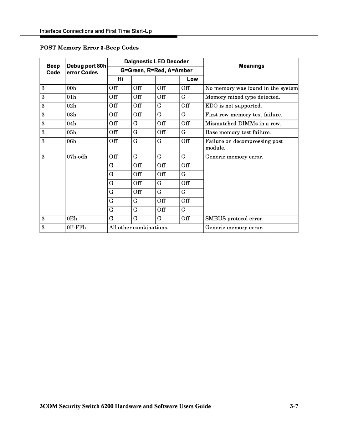
POST Memory Error 3-Beep Codes, Debug port 80h, Daignostic LED Decoder, Meanings
Models:
6200
1
25
78
78
Download
78 pages
59.42 Kb
22
23
24
25
26
27
28
29
Page 25
Image 25
Page 24
Page 26
Page 25
Image 25
Page 24
Page 26
Contents
10/100
Security Switch Hardware and Software Users Guides
10/100/1000
FIBER
ENVIRONMENTAL STATEMENT
UNITED STATES GOVERNMENT LEGEND
End of Life Statement
Regulated Materials Statement
Installation
Contents
3COM Security Switch 6200 Hardware and Software Users Guide
About this Guide
Technical Specifications
4 Configuring the Security Switch 6200 System
5 Upgrading the System Software
Technical Support
Regulatory Information
Connector Pin Assignments
Safety
Regulatory Standards Compliance
3COM Security Switch 6200 Hardware and Software Users Guide
Intended
About this Guide
Audience
Conventions
Security Switch 6200 Product Release Notes
3COM Security Switch 6200 Hardware and Software Users Guide
Install Server Installation and Configuration Guide
Security Switch 6200 Applications Guide
System
Introduction
Components
Figure 1-1 6200 Front View
Chassis
Figure 1-2 Rear Panel Component Layout
Management Options
Configuration Tool
First Time Startup Interview
Introduction
Before You Start
Installation
Requirement
Site Requirements
Description
MGMT1 MGMT2 SYS HDD
Figure 2-1 3COM Security Switch 6200 Shipping Contents
10/100
FIBER
Tools
Additional Equipment Required Equipment
Cables
Table 2-1 Cable Distance Limitations
Terminal or PC
Installation
Front Rack Mounting
Figure 2-2 Front Rack Mounting the Chassis
Tabletop Mounting
Making Connections
Interface Connections and First Time Start-Up
Management Serial Port Connections
Connecting a Terminal or PC to the System Front Serial Craft Port
Power Connections
Connecting Remotely
Figure 3-2 Connecting to the System Remotely
Figure 3-3 System Rear View Power Connections
Normal
Startup and
Operation
LED Displays
BIOS Generated POST Error Beep Codes
POST Error Beep Codes
Error message
BMC Generated POST Beep Codes
Interface Connections and First Time Start-Up
error Codes
POST Memory Error 3-Beep Codes
Beep
Debug port 80h
First Time Startup
3. Define the Time Zone
5. Define the Management Services
3-10
6. Configure the SNMP parameters
4. Select a region
7. Configure the individual user accounts
3-11
The following is an example display showing configured users
8. Configure the host interfaces
9. Configure all additional interfaces
3-12
10. Configure your default gateway
11. Configure NTP to achieve time synchronization
3-13
3-14
Configuring the Security Switch System
Parameters
Configuring
choices. The Enter key is used to select default values
2. To change any of the system parameters enter y, or press the Return key to leave system parameters unchanged
5. Define the Management Services
Configuring User Accounts
the Network
Resolution
Time Protocol
Domain Name
To configure SNMP 1. Select Option 5 from the main menu
Configuring the Simple Network Management Protocol SNMP
2. Configure SNMP Servers. For example
3. Enter the desired option or enter X to return to the main menu
4. Configure SNMP Communities. For example
6. Configure SNMP Trap Destinations. For example
4-10
Interfaces
4-11
1. Select Option 7 from the main menu
4-12
4-13
Configuring Network Interfaces
4-14
IP Aliases
interface. To configure IP Aliases
4-15
4-16
Configuring Static Routes
4-17
Configuring Static ARP Entries
4-18
Configuring the Virtual Router Redundancy Protocol VRRP
4-19
4-20
Configuration
Saving Your System Configuration
Exiting from the Configuration Tool
Restoring
address=10.1.1.50 data /dnsserver
4-22
ipinterface data ifname=management 1 address=192.168.10.6 /data
4-23
ipaddr=128.205.1.31 macaddr=0000a2000003 /data statichost account
4-24
Settings
Default
system to
Factory
4-26
Upgrading the System Software
Upgrading the System Software
Answer Y when this command prompts you
Rollback Features
Upgrading the System Software Using the Safe Upgrade and
Software Safe Upgrade
Upgrading from Version
6. Savew the partition table by entering the letter “w”
Upgrading from Version 2.1 and Greater
Upgrading from Software to a UP While an RP is Operational Rollback
Technical Support
Services
Online
Technical
Support from
3Com Knowledgebase Web Services
Your Network
Supplier
Email Support
Support from 3Com
Telephone Support
Asia, Pacific Rim
Country
Telephone Support Numbers
Telephone Number
Asia, Pacific Rim
North America
Latin America
Returning Products for Repair
Fax Numbers for return authorization numbers
Technical Support
3COM Security Switch 6200 Hardware and Software Users Guide
Country
Telephone Number
Technical Support
Physical Characteristics
Technical Specifications
Environmental Characteristics
Power Characteristics
Technical Specifications
DB-9 Connector
Connector Pin Assignments
Signal
Pin Number
Connector Pin Assignments
Regulatory Information
Safety
Regulatory Standards Compliance
CE marking for the EEA European Economic Area
Immunity Compliance
EMI Compliance
Radio Frequency Interference
VCCI Statement V-3/2000.04
Top
Page
Image
Contents