36CHAPTER 5: USING THE MODEM
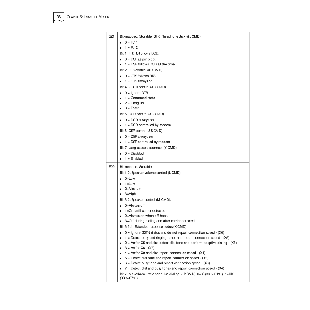
S21
■0 = RJ11
■1 = RJ12
Bit 1. IF DRS Follows DCD:
■0 = DSR as per bit 6.
■1 = DSR follows DCD all the time.
Bit 2. CTS control (&R CMD)
■0 = CTS follows RTS
■1 = CTS always on
Bit 4,3. DTR control (&D CMD)
■0 = Ignore DTR
■1 = Command state
■2 = Hang up
■3 = Reset
Bit 5. DCD control (&C CMD)
■0 = DCD always on
■1 = DCD controlled by modem
Bit 6. DSR control (&S CMD)
■0 = DSR always on
■1 = DSR controlled by modem
Bit 7. Long space disconnect (Y CMD)
■0 = Disabled
■1 = Enabled
S22
Bit 1,0. Speaker volume control (L CMD)
■0=Low
■1=Low
■2=Medium
■3=High
Bit 3,2. Speaker control (M CMD).
■0=Always off
■1=On until carrier detected
■2=Always on when off hook
■3=Off during dialing and after carrier detected.
Bit 6,5,4. Extended response codes (X CMD)
■0 = Ignore GSTN status and do not report connection speed - (X0)
■1 = Detect busy and ringing tones and report connection speed - (X5)
■2 = As for X5 and also detect dial tone and perform adaptive dialing - (X6)
■3 = As for X6 - (X7)
■4 = As for X0 and also report connection speed - (X1)
■5 = Detect dial tone and report connection speed - (X2)
■6 = Detect busy tone and report connection speed - (X3)
■7 = Detect dial and busy tones and report connection speed - (X4)
Bit 7. Make/break ratio for pulse dialing (&P CMD). 0= S (39%/61%). 1=UK (33%/67%)
