S Registers 39
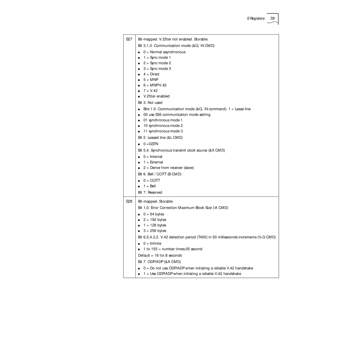
S27
Bit 3,1,0. Communication mode (&Q, \N CMD)
■0 = Normal asynchronous
■1 = Sync mode 1
■2 = Sync mode 2
■3 = Sync mode 3
■4 = Direct
■5 = MNP
■6 = MNP/V.42
■7 = V.42
■V.25ter enabled
Bit 3. Not used
■Bits
■00 use S36 communication mode setting
■01 synchronous mode 1
■10 synchronous mode 2
■11 synchronous mode 3
Bit 2. Leased line (&L CMD)
■0 =GSTN
Bit 5,4. Synchronous transmit clock source (&X CMD)
■0 = Internal
■1 = External
■2 = Derive from receiver (slave)
Bit 6. Bell / CCITT (B CMD)
■0 = CCITT
■1 = Bell
Bit 7. Reserved
S28
Bit 1,0. Error Correction Maximum Block Size (\A CMD)
■0 = 64 bytes
■2 = 192 bytes
■1 = 128 bytes
■3 = 256 bytes
Bit 6,5,4,3,2. V.42 detection period (T400) in 50 milliseconds increments (%G CMD)
■0 = Infinite
■1 to 155 = number times.05 second
Default = 16 for.8 seconds
Bit 7. ODP/ADP (&A CMD)
■0 = Do not use ODP/ADP when initiating a reliable V.42 handshake
■1 = Use ODP/ADP when initiating a reliable V.42 handshake