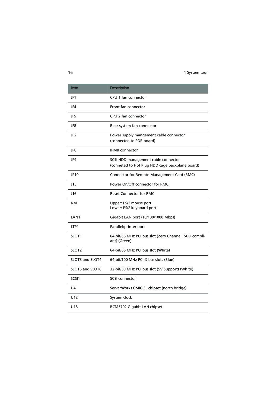
16 | 1 System tour |
|
|
Item | Description |
|
|
JF1 | CPU 1 fan connector |
|
|
JF4 | Front fan connector |
|
|
JF5 | CPU 2 fan connector |
|
|
JF8 | Rear system fan connector |
|
|
JP2 | Power supply mangement cable connector |
| (connected to PDB board) |
|
|
JP8 | IPMB connector |
|
|
JP9 | SCSI HDD management cable connector |
| (conneted to Hot Plug HDD cage backplane board) |
|
|
JP10 | Connector for Remote Management Card (RMC) |
|
|
J15 | Power On/Off connector for RMC |
|
|
J16 | Reset Connector for RMC |
|
|
KM1 | Upper: PS/2 mouse port |
| Lower: PS/2 keyboard port |
|
|
LAN1 | Gigabit LAN port (10/100/1000 Mbps) |
|
|
LTP1 | Parallel/printer port |
|
|
SLOT1 | |
| ant) (Green) |
|
|
SLOT2 | |
|
|
SLOT3 and SLOT4 | |
|
|
SLOT5 and SLOT6 | |
|
|
SCSI1 | SCSI connector |
|
|
U4 | ServerWorks |
|
|
U12 | System clock |
|
|
U18 | BCM5702 Gigabit LAN chipset |
|
|
Page 26
Image 26
