Manuals
/
Brands
/
Computer Equipment
/
Personal Computer
/
Acer
/
Computer Equipment
/
Personal Computer
Acer
Z5600, Z5610
- page 112
1
112
210
210
Download
210 pages, 7.5 Mb
102
Chapter 3
Replacing the RAM Cover
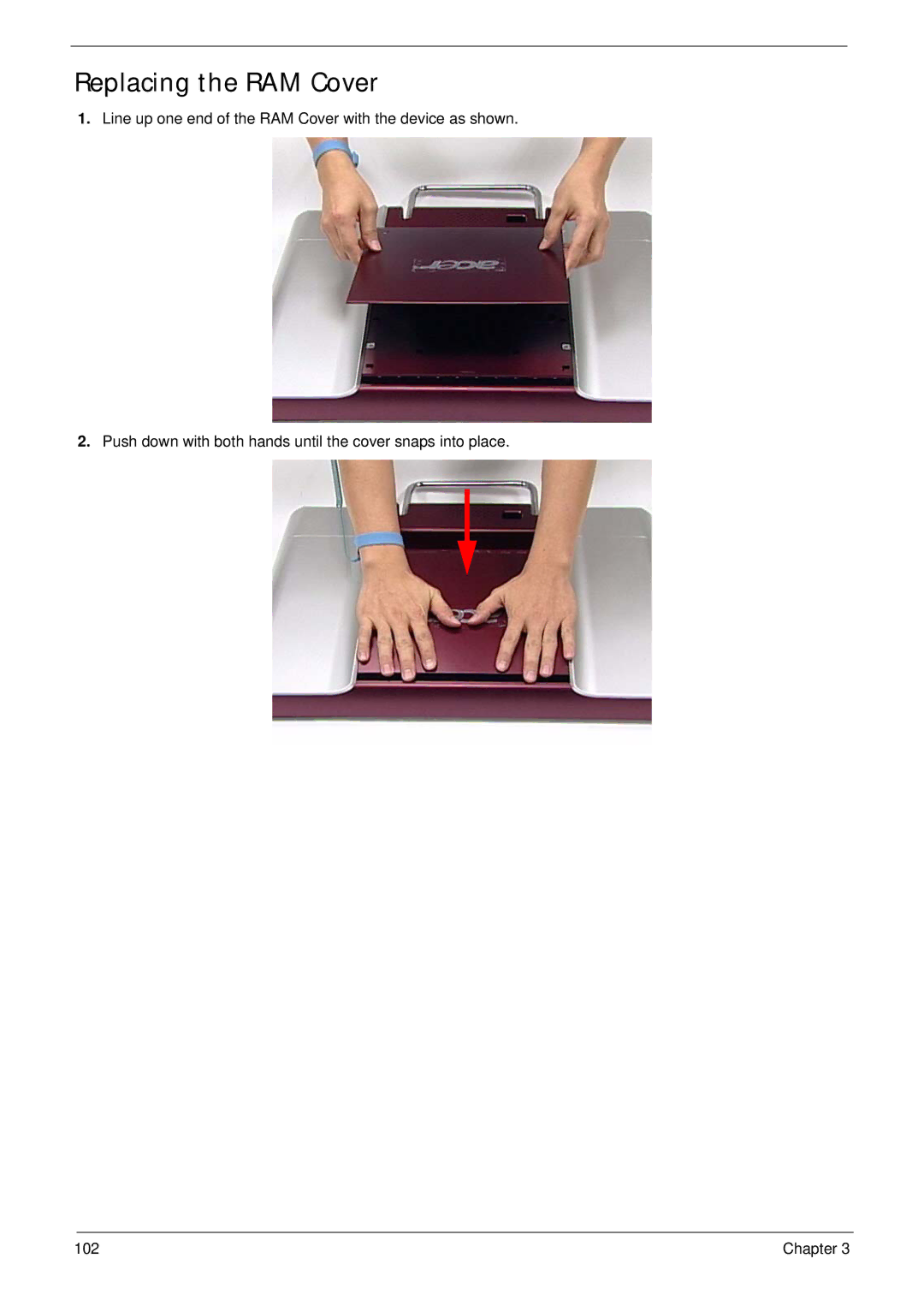
1.
Line up one end of the RAM Cover with the device as shown.
2.
Push down with both hands until the cover snaps into place.
Contents
Main
Page
Copyright
Disclaimer
Conventions
Preface
Page
System Specifications 1
System Utilities 17
Machine Disassembly and Replacement 33
Troubleshooting 103
Jumper and Connector Locations 117
FRU (Field Replaceable Unit) List 123
Page
Page
System Specifications
Chapter 1
Features
Operating System
Platform
Communication
Graphics
I/O interface
Environment
Chapter 1 3
System Block Diagram
ITE8512
+12V
VCC_CORE GMCH_CORE VCC1.1
Intel Yorkfield/Wolfdale Q9000/E8000 LGA775
Your Acer Computer tour
Front View
Right View
Page
Rear View
Using the Keyboard
Windows Keys
Hardware Specifications and Configurations
Page
Page
Page
Page
Page
Page
System Utilities
Chapter 2
BIOS Setup Utility
Navigating the BIOS Utility
Information
Main
SATA Port 1
SATA Port 2
SATA Port 4
Advanced
Advanced Chipset Features
Integrated Peripherals
Security
Page
Page
PC Health
Power
Boot
Exit
Machine Disassembly and Replacement
Chapter 3
Disassembly Requirements
General Information
Pre-disassembly Instructions
Disassembly Process
Disassembly Flowchart
Page
Page
Page
Page
Page
Page
Page
Page
Page
Page
Page
Page
Page
Page
Page
Page
Page
Page
Page
Page
Page
Page
Page
Page
Page
Page
Page
Removing the Mainboard Cables
Page
Page
Page
Page
Page
Removing the LCD Bracket
Page
Page
Page
Page
Page
Replacing the Mainboard Cables
Page
Page
Page
Page
Page
Page
Page
Page
Page
Page
Page
Page
Page
Page
Page
Page
Page
Page
Page
Replacing the Back Frame
c
A
B
Page
Page
Page
Page
Page
Page
Page
Page
Troubleshooting
Chapter 4
Common Problems
ODD Failure
ODD Not Operating Correctly
Discs Do Not Play
Discs Do Not Burn Properly
Playback is Choppy
Drive Not Detected
Drive Read Failure
Chapter 4 107
Wireless Failure
If the wireless functionality fails, use the following flowchart to determine the required action:
108 Chapter 4
Camera Failure
If the camera functionality fails, use the following flowchart to determine the required action:
Speaker Failure
Sound Problems
Page
LCD Failure
No POST or Video
Abnormal Video Display
General Troubleshooting Issues
Computer Shutsdown Intermittently
Random Loss of BIOS Settings
Microphone Problems
HDD Not Operating Correctly
External Mouse Failure
Page
Intermittent Problems
Undetermined Problems
Jumper and Connector Locations
Chapter 5
Top View
Page
Clearing Password Check and BIOS Recovery
Clearing Password Check
Hardware Open Gap Description
Steps for Clearing BIOS Password Check
BIOS Recovery by Crisis Disk
BIOS Recovery Boot Block:
BIOS Recovery Hotkey:
Steps for BIOS Recovery from USB Storage:
Steps for BIOS Recovery by Crisis Disk:
Page
FRU (Field Replaceable Unit) List
Chapter 6
Aspire Z5600/Z5610 Series Exploded Diagrams
Main Assembly
Page
FRU List
Page
Page
Page
Page
Page
Page
Screw List
Page
Page
Model Definition and Configuration
Appendix A
Aspire Z5600/Z5610 Series
Page
Page
Page
Page
Page
Page
Page
Page
Page
Page
Page
Page
Page
Page
Page
Page
Page
Page
Page
Page
Page
Page
Page
Page
Page
Page
Page
Page
Page
Page
Page
Page
Page
Page
Page
Page
Page
Page
Page
Page
Page
Page
Page
Page
Page
Page
Page
Page
Page
Page
Page
Microsoft Windows 7 Environment Test
Page
Page
Page
Page
Page
Page
Page
Page
Online Support Information
Appendix C
Page
Index
A
B
M
C
O
P
S
T
U