Section 1 TRACER Description
E1 Interfaces
The E1 interfaces conform to the ITU G.703 and G.704 electrical and signaling interface recommendations. Two interfacing configurations are allowed - two pair of BNC coaxial connectors or two
The coaxial connection provides a 75Ω unbalanced connection. The shield of the TX coaxial connection is attached to earth ground. A strap is provided to optionally connect the shield of the RX coaxial connection to ground as described in G.703. The 15 pin
TRACER System Configuration
A TRACER system is composed of three major subsystems
Baseband Processor or BBP
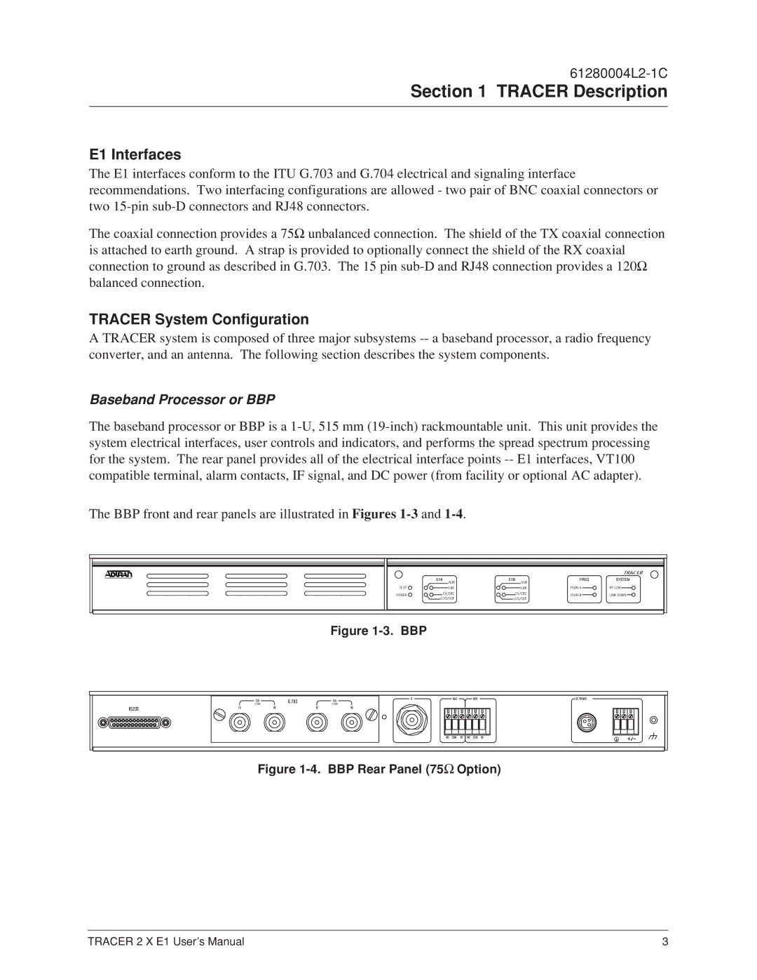
The baseband processor or BBP is a
The BBP front and rear panels are illustrated in Figures
| E1A | E1B | FREQ | SYSTEMTRACER |
| ALM | ALM |
|
|
TEST | LBK | LBK | PLAN A | RF LOW |
POWER | CV/CRC | CV/CRC | PLAN B | LINK DOWN |
| LOS/OOF | LOS/OOF |
|
|
Figure 1-3. BBP
RS232
75 OHM | G.703 |
| 75 OHM | IF | MAJ | MIN | DC POWER |
E1B |
|
| E1A |
|
|
|
|
TX | RX | TX |
| RX |
|
|
|
|
|
|
| NO | COM NC | NO COM | NC |
Figure 1-4. BBP Rear Panel (75Ω Option)
TRACER 2 X E1 User’s Manual | 3 |
