Section 1 TRACER Description
Built-In Tests
The TRACER has several features to aid in site setup and later debugging. These diagnostics include E1 loopbacks and a link test with BERT (Bit Error Rate Test) data. A link test is performed by pressing the test button. The remote unit will then send a pseudorandom data pattern, and the local end will compute a BER. After the conclusion of the test, the remote end will automatically be instructed to terminate the pattern generation. If any bit errors are introduced, the Remote Test Fail LED will illuminate.
Radio Frequency Converter or RFC
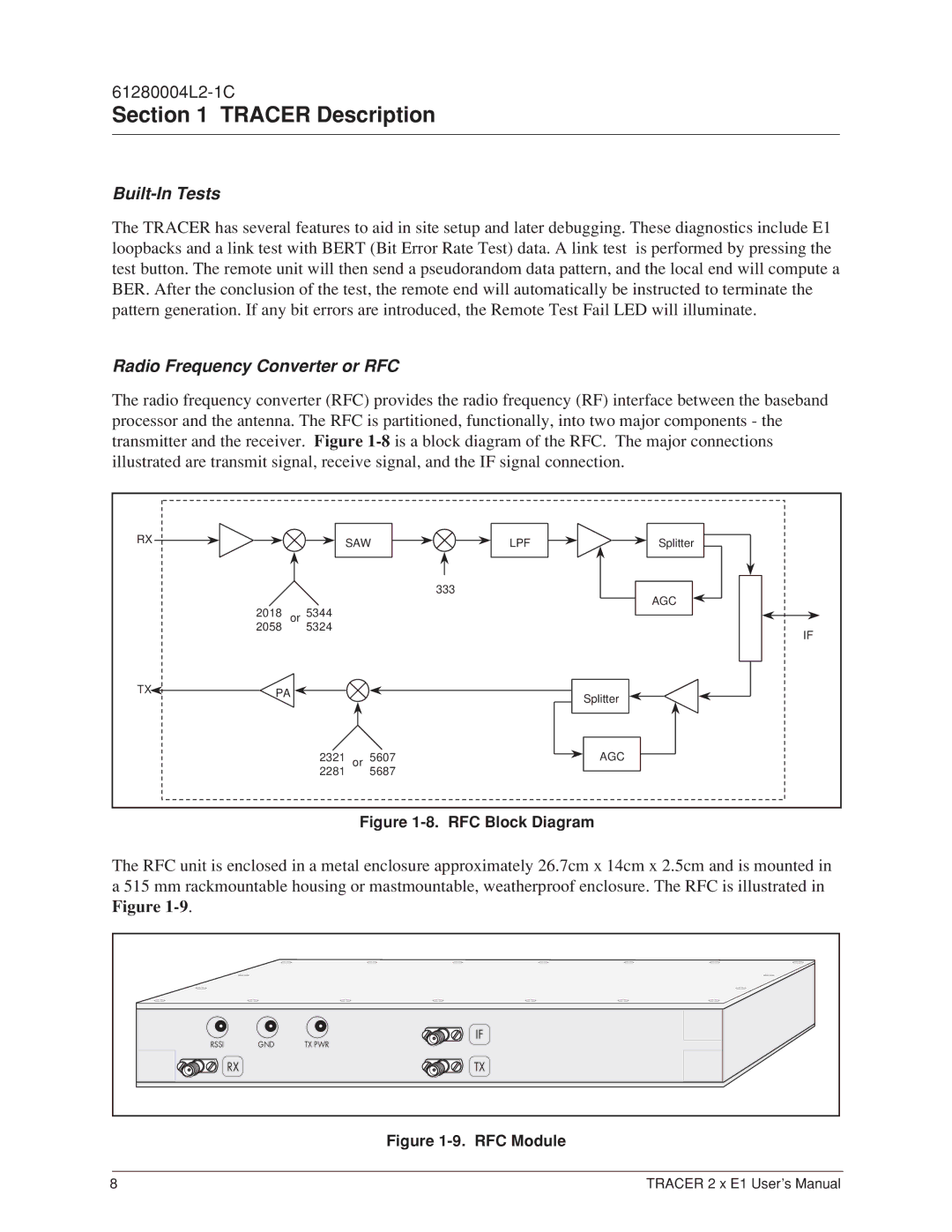
The radio frequency converter (RFC) provides the radio frequency (RF) interface between the baseband
processor and the antenna. The RFC is partitioned, functionally, into two major components - the |
|
| |||||||||||||||||||||||||||||||||||||||||
transmitter and the receiver. Figure |
|
| |||||||||||||||||||||||||||||||||||||||||
illustrated are transmit signal, receive signal, and the IF signal connection. |
|
|
|
|
|
|
|
|
|
|
|
|
|
|
| ||||||||||||||||||||||||||||
| RX |
|
|
|
|
|
|
|
| SAW |
| 333 |
|
| LPF |
|
|
|
|
|
|
|
|
|
|
|
| Splitter |
|
|
|
|
|
|
|
|
| ||||||
|
|
|
|
|
|
|
|
|
| ||||||||||||||||||||||||||||||||||
|
|
|
|
|
| 53244 |
|
|
|
|
| AGC |
|
|
|
| |||||||||||||||||||||||||||
|
|
|
|
|
|
|
|
|
|
|
|
|
|
|
|
|
|
|
|
|
|
|
|
|
|
|
|
|
|
|
|
|
|
|
| ||||||||
|
| 20518 |
|
|
|
|
|
|
|
|
|
|
| ||||||||||||||||||||||||||||||
|
|
|
|
|
|
|
|
|
|
|
|
|
|
|
|
|
|
|
|
|
|
|
|
|
|
|
|
|
|
|
|
|
| ||||||||||
|
|
|
|
|
|
|
|
|
|
|
|
|
|
|
|
|
|
|
|
|
|
|
|
|
|
|
|
|
|
|
|
|
|
|
| ||||||||
|
|
|
|
|
|
|
|
|
|
|
|
|
|
|
|
|
|
|
|
|
|
|
|
|
|
|
|
|
|
|
|
|
|
|
| ||||||||
|
|
| or |
|
|
|
|
|
|
|
|
|
|
|
|
|
|
|
|
|
|
|
|
|
|
|
|
|
|
|
|
|
|
|
|
|
|
| |||||
|
|
|
|
|
|
|
|
|
|
|
|
|
|
|
|
|
|
|
|
|
|
|
|
|
|
|
|
|
|
|
|
|
|
|
|
|
| ||||||
| TX |
|
|
|
|
|
|
|
|
|
|
|
|
|
|
|
|
|
|
|
|
|
|
|
|
|
|
|
|
|
|
|
|
| IF | ||||||||
|
|
| PA |
|
|
|
|
|
|
|
|
|
|
|
|
|
|
| Splitter |
|
|
|
|
|
|
|
|
|
|
|
|
|
|
|
|
| |||||||
|
|
|
|
|
|
|
|
|
|
|
|
|
|
|
|
|
|
|
|
|
|
|
|
|
|
|
|
|
|
|
|
|
|
| |||||||||
|
|
|
|
|
|
|
|
|
|
|
|
|
|
|
| AGC |
|
|
|
|
|
|
|
|
|
|
|
|
|
|
|
| |||||||||||
|
|
| 223821 | or56807 |
|
|
|
|
|
|
|
|
|
|
|
|
|
|
|
|
|
|
|
|
|
|
|
|
|
|
|
|
| ||||||||||
|
|
|
|
|
|
|
|
|
|
|
|
|
|
|
|
|
|
|
|
|
|
|
|
|
|
|
|
|
|
|
|
|
| ||||||||||
|
|
|
|
|
|
|
|
|
|
|
|
|
|
|
|
|
|
|
|
|
|
|
|
|
|
|
|
|
|
|
|
|
|
|
| ||||||||
|
|
|
|
|
|
|
|
|
|
|
|
|
|
|
|
|
|
|
|
|
|
|
|
|
|
|
|
|
|
|
|
|
|
|
|
|
| ||||||
|
|
|
|
|
|
|
|
|
|
|
|
|
|
|
|
|
|
|
|
|
|
|
|
|
|
|
|
|
|
|
|
|
|
|
|
|
|
| |||||
|
|
|
|
|
|
|
|
|
|
|
|
|
|
|
|
|
|
|
|
|
|
|
|
|
|
|
|
|
|
|
|
|
|
|
|
|
|
| |||||
Figure 1-8. RFC Block Diagram
The RFC unit is enclosed in a metal enclosure approximately 26.7cm x 14cm x 2.5cm and is mounted in a 515 mm rackmountable housing or mastmountable, weatherproof enclosure. The RFC is illustrated in
Figure |
|
|
|
| IF |
RSSI | GND | TX PWR |
| RX | TX |
Figure 1-9. RFC Module
8 | TRACER 2 x E1 User’s Manual |
