Section 1 TRACER Description
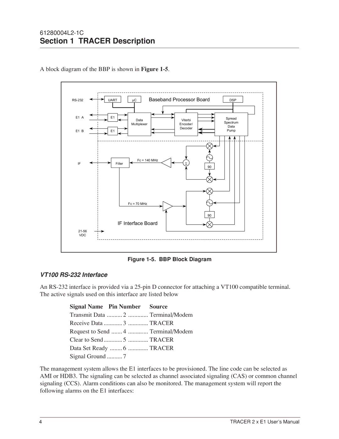
A block diagram of the BBP is shown in Figure 1-5.
UART | µC | Baseband Processor Board | DSP | |
E1 A | E1 | Data | Viterbi | Spread |
|
| |||
|
| Spectrum | ||
|
| Multiplexer | Encoder/ | |
|
| Data | ||
|
|
| Decoder | |
E1 B | E1 |
| Pump | |
|
| |||
|
| Fc = 140 MHz |
| |
IF | Filter | Σ |
| |
|
|
| 90 |
|
|
| Fc = 70 MHz |
|
|
|
|
| 90 |
|
|
| IF Interface Board |
| |
|
|
|
| |
VDC |
|
|
|
|
Figure 1-5. BBP Block Diagram
VT100 RS-232 Interface
An
Signal Name Pin Number | Source | |
Transmit Data | 2 | Terminal/Modem |
Receive Data | 3 | TRACER |
Request to Send | 4 | Terminal/Modem |
Clear to Send | 5 | TRACER |
Data Set Ready | 6 | TRACER |
Signal Ground | 7 |
|
The management system allows the E1 interfaces to be provisioned. The line code can be selected as AMI or HDB3. The signaling can be selected as channel associated signaling (CAS) or common channel signaling (CCS). Alarm conditions can also be monitored. The management system will report the following alarms on the E1 interfaces:
4 | TRACER 2 x E1 User’s Manual |