SECTION 1 TRACER DESCRIPTION
INTRODUCTION
The Dual E1 version of TRACER provides two, individual E1 transports via a 2.4 GHz or 5.8 GHz, direct sequence, spread spectrum microwave link. The transmitter output power is 20 dBm maximum while the receiver sensitivity is
Applications
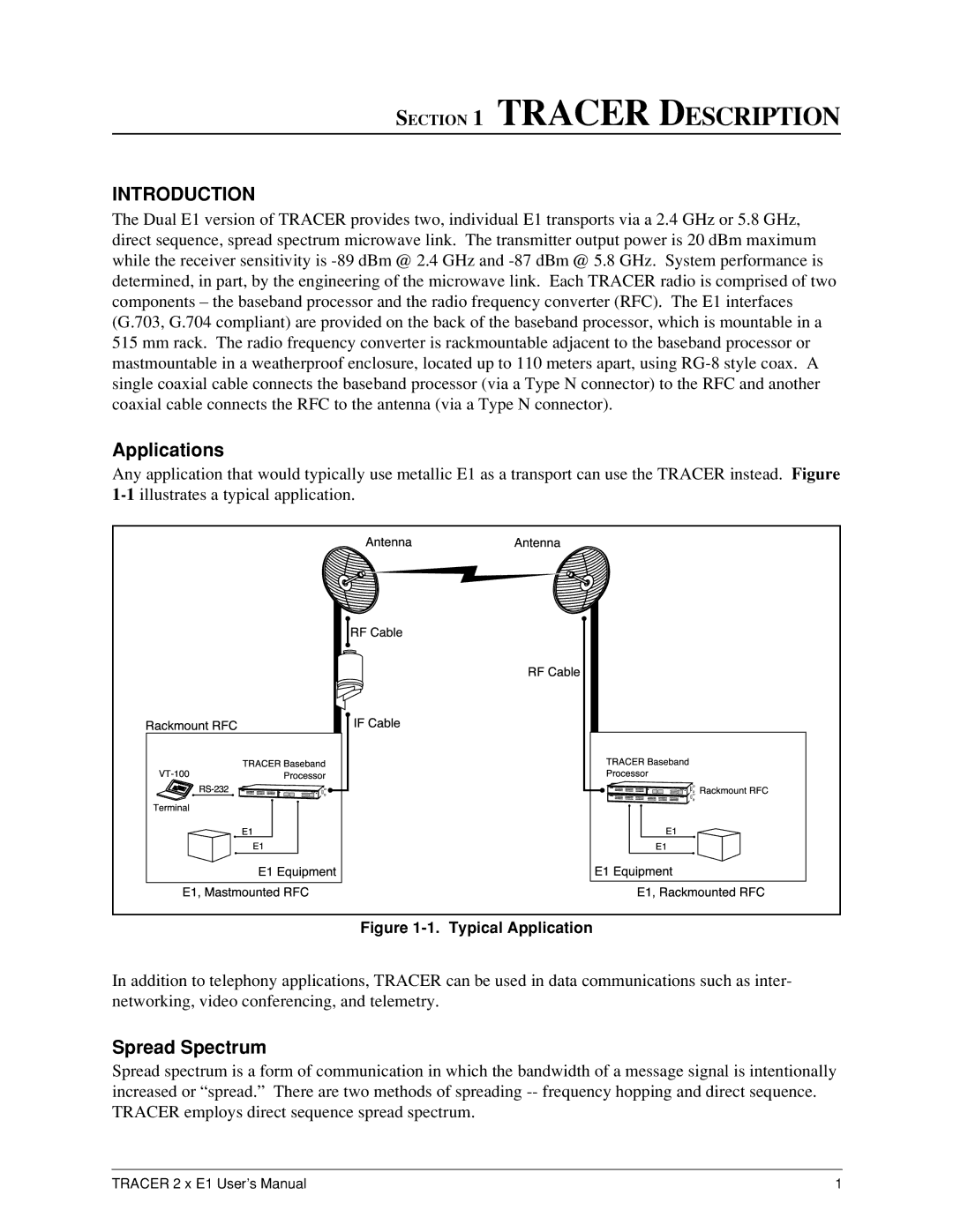
Any application that would typically use metallic E1 as a transport can use the TRACER instead. Figure | ||||||
Antenna |
|
| ||||
RackmountRFC |
|
| RFCable | RFCable |
|
|
TRACERBaseband | IFCable | TRACERBaseband |
| |||
|
|
| ||||
| Processor | E1 | RackmountRFC | |||
E1 | Processor |
|
| |||
E1,MastmountedE1E1EquRFCipment |
| E1EquipmentE1,E1RackmountedRFC | ||||
Figure 1-1. Typical Application
In addition to telephony applications, TRACER can be used in data communications such as inter- networking, video conferencing, and telemetry.
Spread Spectrum
Spread spectrum is a form of communication in which the bandwidth of a message signal is intentionally increased or “spread.” There are two methods of spreading
TRACER 2 x E1 User’s Manual | 1 |
