Section 1 TRACER Description
| E1A | E1B | FREQ | SYSTEMTRACER | |
| ALM | ALM |
|
| |
TEST | LBK | LBK | PLAN A | RF LOW | |
POWER | CV/CRC | CV/CRC | PLAN B | LINK DOWN | |
LOS/OOF | LOS/OOF | ||||
|
|
|
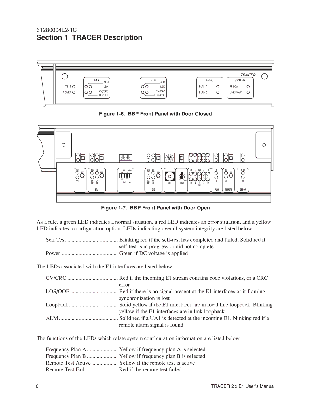
Figure 1-6. BBP Front Panel with Door Closed
1 2 3 4
1 | 2 |
| |
0 |
|
9 8
3 |
|
4 | |
| 5 |
7 | 6 |
| |
TEST | ALM | LBK | HDB3 | HDB3 | ALM | LBK | |
| RESET | LBKA | CAS | CAS |
| LBKB | |
PWR | LOS | CV | CCS | CCS | LOS | CV | |
AMI | AMI | ||||||
| OOF | CRC | OOF | CRC | |||
|
|
|
|
| GND | L | RSSI | +5 | +12 | A | TST | RF LOW |
|
|
|
|
|
|
|
|
| TEST |
| UP |
|
|
|
|
|
|
|
|
CODE | DOWN | CLK | Q | RF | B | FAIL | LINK | ||
TX PWR |
|
|
| ||||||
|
|
|
| PWR |
|
|
|
|
|
E1A | E1B | PLAN | REMOTE | ERROR |
Figure 1-7. BBP Front Panel with Door Open
As a rule, a green LED indicates a normal situation, a red LED indicates an error situation, and a yellow LED indicates a configuration option. LEDs indicating overall system integrity are listed below.
Self Test | Blinking red if the |
| |
Power | Green if DC voltage is applied |
The LEDs associated with the E1 interfaces are listed below.
CV/CRC | Red if the incoming E1 stream contains code violations, or a CRC |
| error |
LOS/OOF | Red if there is no signal present at the E1 interfaces or if framing |
| synchronization is lost |
Loopback | Solid yellow if the E1 interfaces are in local line loopback. Blinking |
| yellow if the E1 interfaces are in link loopback. |
ALM | Solid red if a UA1 is detected at the incoming E1, blinking red if a |
| remote alarm signal is found |
The functions of the LEDs which relate system configuration information are listed below.
Frequency Plan A | Yellow if frequency plan A is selected |
Frequency Plan B | Yellow if frequency plan B is selected |
Remote Test Active | Yellow if the remote test is active |
Remote Test Fail | Red if the remote test failed |
6 | TRACER 2 x E1 User’s Manual |
