Appendix E: Connector Pinouts
|
|
|
|
|
|
|
|
|
|
| Table | |
|
|
|
|
|
|
|
|
|
|
|
| |
|
|
|
|
|
|
|
|
| ||||
Pin | Name |
|
|
|
| I/O | Description |
| ||||
1 | Shield |
|
|
|
| I/O | Shield for cable |
| ||||
2 | DPR |
|
|
|
| I | Digit Present |
| ||||
3 | ACR |
|
|
|
| O | Abandon Call and Retry |
| ||||
4 | CRQ |
|
|
|
| I | Call Request |
| ||||
5 | PND |
|
|
|
| O | Present Next Digit |
| ||||
6 | PWI |
|
|
|
| O | Power Indication |
| ||||
7 | SG |
|
|
|
| I/O | Signal Ground |
| ||||
13 | DSC |
|
|
|
| O | Distant Station Connect |
| ||||
14 | NB1 |
|
|
|
| I | Digit LSB |
| ||||
15 | NB2 |
|
|
|
| I | Digit bit 2 |
| ||||
16 | NB4 |
|
|
|
| I | Digit bit 3 |
| ||||
17 | NB8 |
|
|
|
| I | Digit bit MSB |
| ||||
22 | DLO |
|
|
|
| O | Data Line Occupied |
| ||||
NC |
|
|
|
| N/A | No Connection |
| |||||
NC |
|
|
|
| N/A | No Connection |
| |||||
NC |
|
|
|
| N/A | No Connection |
| |||||
I = Input | O = Output | N/A = Not Applicable |
| |||||||||
| PIN 1 |
| PIN 8 |
|
| |||||||
|
|
|
|
|
|
|
|
|
|
|
|
|
|
|
|
|
|
|
|
|
|
|
|
|
|
|
|
|
|
|
|
|
|
|
|
|
|
|
|
|
|
|
|
|
|
|
|
|
|
|
|
|
|
|
|
|
|
|
|
|
|
|
|
|
|
|
|
|
|
|
|
|
|
|
|
|
|
ISDN
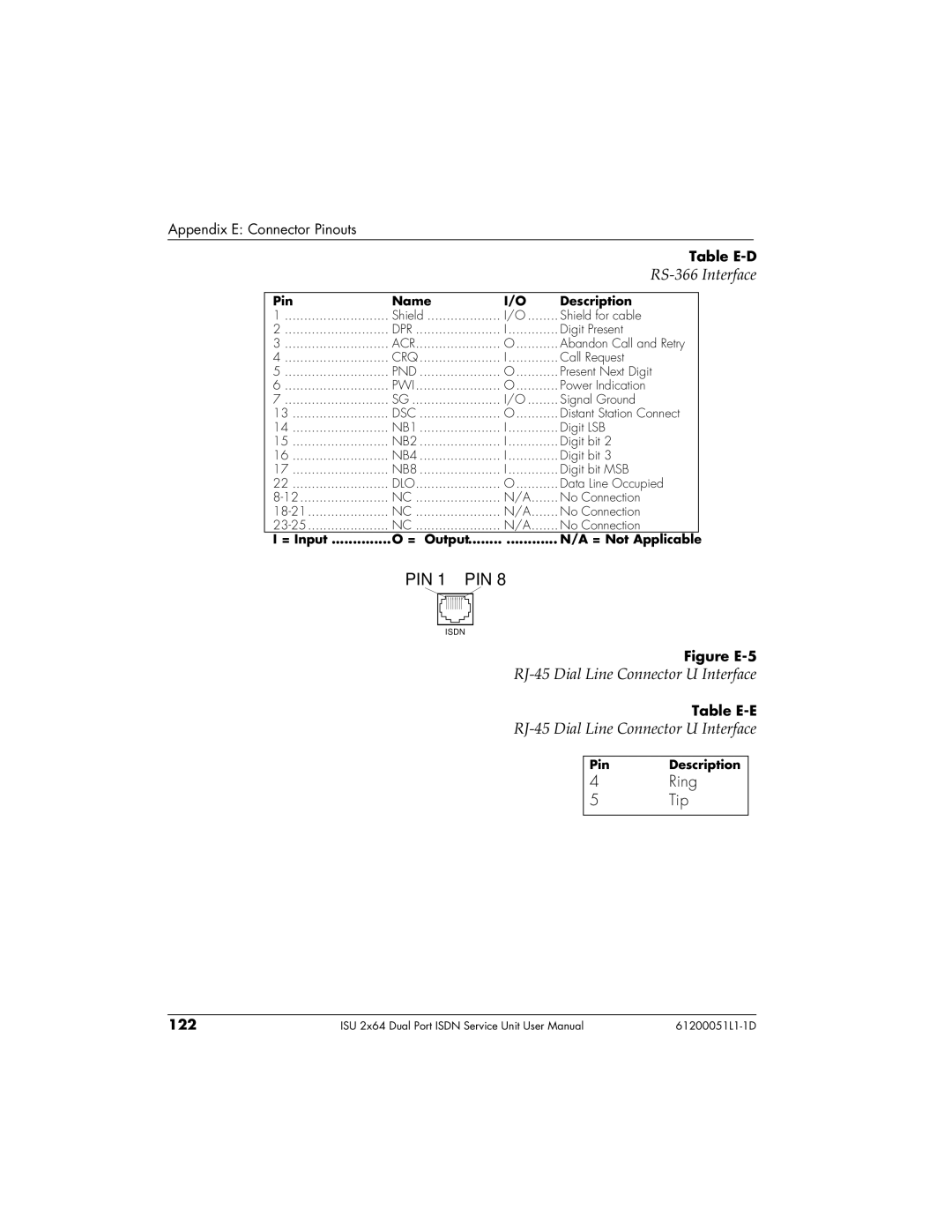
Figure E-5
RJ-45 Dial Line Connector U Interface
Table
Pin | Description |
4 | Ring |
5 | Tip |
|
|
122 | ISU 2x64 Dual Port ISDN Service Unit User Manual |