Manuals
/
Brands
/
Computer Equipment
/
Laptop
/
Advantech
/
Computer Equipment
/
Laptop
Advantech
IPPC-9120, IPPC-9150
- page 74
1
74
163
163
Download
163 pages, 5.4 Mb
Chapter 5 PCI SVGA Setup
59
5.2.2 Installation for Windows 98
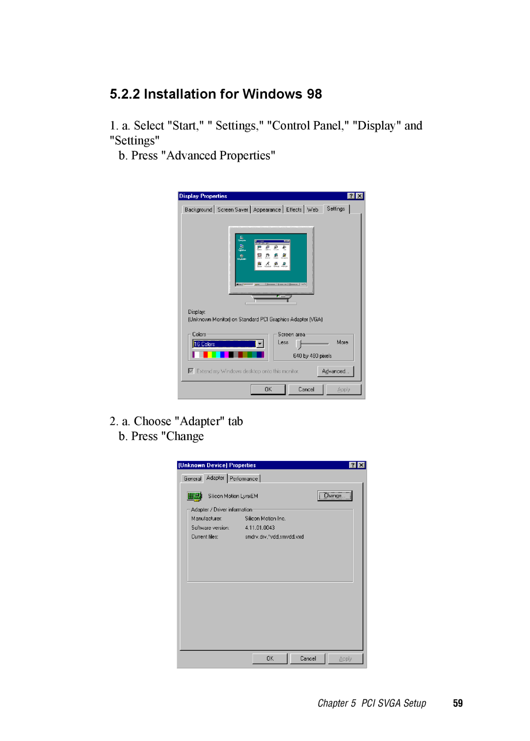
1. a. Select "Start," " Settings," "Control Panel," "Display" and
"Settings"
b. Press "Advanced Properties"
2. a. Choose "Adapter" tab
b. Press "Change
Contents
Main
Copyright notice
Acknowledgments
FCC Class B
Packing List
Packing List
Additional Information and Assistance
Safety Instructions
Wichtige Sicherheishinweise
Contents
Page
Page
Page
Page
Figures
Tables
Page
1.1 Introduction
1.2 Specifications
General
Standard PC functions
PCI SVGA/flat panel interface
Audio function
PCI bus Ethernet interface
Analog Resistive Touchscreen (optional)
NFI Touchscreen (optional)
Optional modules
Page
Page
Page
System Setup
2.1 A Quick Tour of the IPPC-9120/9150 Series
Page
2.1.1 PS/2 mouse and keyboard
2.1.2 Parallel port
2.1.3 Serial COM ports
2.1.4 VGA port
2.1.5 USB ports
2.1.6 Audio interface
2.1.7 Ethernet
2.1.8 Adjusting the LCD brightness
2.2 Installing SDRAM
2.3 Installing a CPU
Page
2.4 Installing a 2.5" HDD
Page
Page
2.5 Installing a CD-ROM Drive
Page
Page
2.7 Mounting Instructions
2.7.1 Panel mounting
Page
Page
Page
Page
Jumper Settings and Connectors
3.1 Jumpers and Connectors
3.1.1 Setting jumpers
3.1.2 Jumpers and switch
IPPC-9120/9150 Series User's Manual
3.1.3 Locating jumpers and switch
Figure 3-1: Locating jumpers on the IPPC-9120/9150 motherboard
3.1.4 Connectors
IPPC-9120/9150 Series User's Manual
3.1.5 Locating connectors
Figure 3-2: Locating connectors on the IPPC-9120/9150 motherboard
3.2 CPU Installation
3.3 COM-port Interface
3.3.1 COM2 RS-232/422/485 setting (JP3, JP4, JP5)
3.3.2 COM1 / COM2 pin 9 output type setting (JP9)
Note: Pins 1, 3 and 5 are for COM1. Pins 2, 4 and 6 are for COM2.
Chapter 3 Jumper Settings and Connectors
37
3.3.3 COM3 / COM4 pin 9 output type setting (JP6)
3.4 CMOS Clear for External RTC (JP8)
Table 3-8: Clear CMOS / External RTC (JP8)
*Normal operation Clear CMOS
3.5 Internal -12 V Source Enable Setting (JP1)
3.6 VGA Interface
3.6.1 LCD panel power setting
3.6.2 Panel type select (SW3)
3.7 Watchdog Timer Configuration
3.7.1 Watchdog activity selection (JP7)
Page
Page
4.1 Introduction
4.2 Installation of Ethernet Driver
Page
Page
Page
Page
Page
Page
Page
Page
Page
Page
Page
5.1 Introduction
5.1.1 Chipset
5.1.2 Display memory
5.1.3 Display types
5.2 Installation of SVGA Driver
Page
Page
Page
Page
Page
Page
Page
Page
Page
Page
Page
Page
Page
6.1 Introduction
6.2 Installation of Audio Driver
Page
Page
Page
Page
Page
Page
Page
7.1 Introduction
7.2 Installation of PCMCIA Driver
Page
Page
Page
8.1 Introduction
8.1.1 General information
8.1.2 Analog Resistive Touchscreen Specifications
8.1.3 NFI Touchscreen Specifications
8.2 Installation of Resistive-type Touchscreen Driver
Page
Page
Page
Page
Page
Page
Page
Page
Page
Page
Page
Page
Page
Page
Page
Page
Page
Page
Page
Page
Page
Page
Page
9.1 Award BIOS Setup
9.2 CMOS Setup Utility
9.3 Standard CMOS Setup
9.3.1 Hard disk configurations
9.4 BIOS Features Setup
Page
Page
Page
9.5 Chipset Features Setup
Page
9.6 Power Management Setup
Page
Page
9.7 PNP/PCI Configuration Setup
9.8 Load BIOS Defaults
9.9 Load Setup Defaults
9.10 Integrated Peripherals
Page
9.11 Password Setting
9.12 IDE HDD Auto Detection
9.13 Save and Exit Setup
9.14 Exit Without Saving
Page
Page
B
B.1 Programming the Watchdog Timer
Appendix B Programming the Watchdog Timer
The following example shows how you might program the watchdog timer in BASIC:
Page
C
Pin Assignments
C.1 AT Power Connector (J1)
C.2 TV Output Connector (J2) (*Reserved)
C.3 Inverter Power Connector (J4)
C.4 Internal Speaker Connector (J6) (*Reserved)
C.5 Front Panel Control Connector (J8) (*Reserved)
C.6 IR Connector (J9) (*Reserved)
C.7 Flat Panel Display Connector (CN2)
C.8 Flat Panel Display Connector (CN3)
C.9 PanelLink Interface (CN4) (*Reserved)
C.10 Floppy Drive Connector (CN10)
C.11 Internal COM4, mouse and touch screen power connector (CN23)
C.12 EIDE Hard Disk Drive Connector (CN16)
# low active
C.13 CD-ROM Connector (CN18)
# low active
C.14 CPU Fan Power Connector (FAN1)
C.15 System Fan Power Connector (FAN2)
Appendix C Pin Assignments
C.16 PCI/ISA Bus Expansion Connector (SLOT1)
side view
Page
Page
Page
Page
C.17 COM2