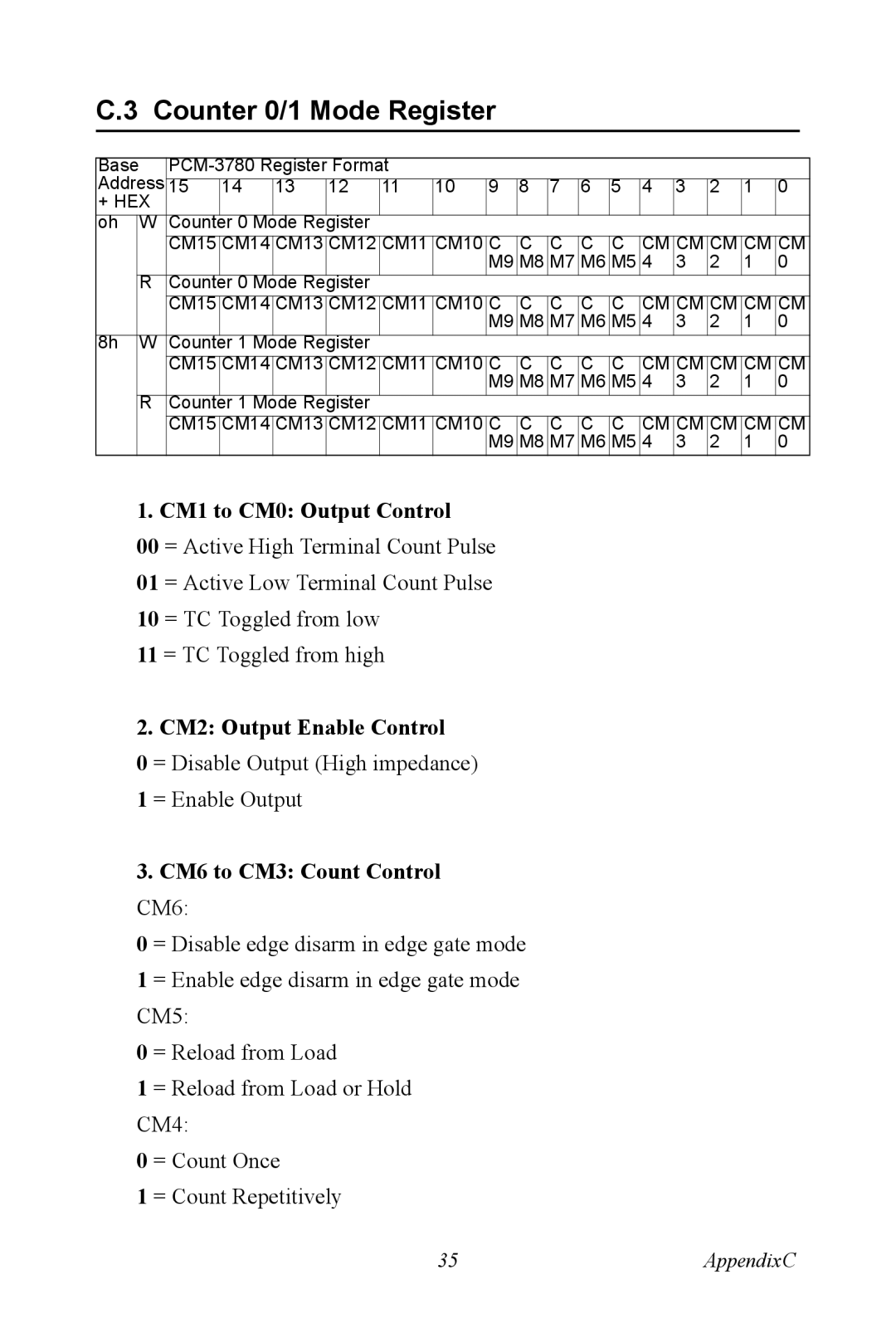
C.3 Counter 0/1 Mode Register
|
|
|
|
|
|
|
|
|
|
|
|
|
| ||||
Base |
|
|
|
|
|
|
|
|
|
|
|
| |||||
Address |
|
|
|
|
|
|
|
|
|
|
|
|
|
|
|
| |
15 | 14 | 13 | 12 | 11 | 10 | 9 | 8 | 7 | 6 | 5 | 4 | 3 | 2 | 1 | 0 | ||
+ HEX |
|
|
|
|
|
|
|
|
|
|
|
|
|
|
|
| |
oh | W | Counter | 0 Mode Register |
|
|
|
|
|
|
|
|
|
|
|
| ||
|
| CM15 | CM14 | CM13 | CM12 | CM11 | CM10 | C | C | C | C | C | CM | CM | CM | CM | CM |
|
|
|
|
|
|
|
| M9 | M8 | M7 | M6 | M5 | 4 | 3 | 2 | 1 | 0 |
| R | Counter | 0 Mode Register |
|
|
|
|
|
|
|
|
|
|
|
| ||
|
| CM15 | CM14 | CM13 | CM12 | CM11 | CM10 | C | C | C | C | C | CM | CM | CM | CM | CM |
|
|
|
|
|
|
|
| M9 | M8 | M7 | M6 | M5 | 4 | 3 | 2 | 1 | 0 |
8h | W | Counter | 1 Mode Register |
|
|
|
|
|
|
|
|
|
|
|
| ||
|
| CM15 | CM14 | CM13 | CM12 | CM11 | CM10 | C | C | C | C | C | CM | CM | CM | CM | CM |
|
|
|
|
|
|
|
| M9 | M8 | M7 | M6 | M5 | 4 | 3 | 2 | 1 | 0 |
| R | Counter | 1 Mode Register |
|
|
|
|
|
|
|
|
|
|
|
| ||
|
| CM15 | CM14 | CM13 | CM12 | CM11 | CM10 | C | C | C | C | C | CM | CM | CM | CM | CM |
|
|
|
|
|
|
|
| M9 | M8 | M7 | M6 | M5 | 4 | 3 | 2 | 1 | 0 |
1. CM1 to CM0: Output Control
00 = Active High Terminal Count Pulse
01 = Active Low Terminal Count Pulse
10 = TC Toggled from low
11 = TC Toggled from high
2. CM2: Output Enable Control
0 = Disable Output (High impedance)
1 = Enable Output
3.CM6 to CM3: Count Control CM6:
0= Disable edge disarm in edge gate mode
1= Enable edge disarm in edge gate mode CM5:
0= Reload from Load
1= Reload from Load or Hold CM4:
0= Count Once
1= Count Repetitively
35 | AppendixC |
