Appendix A Specifications
A.1 Programmable Counter
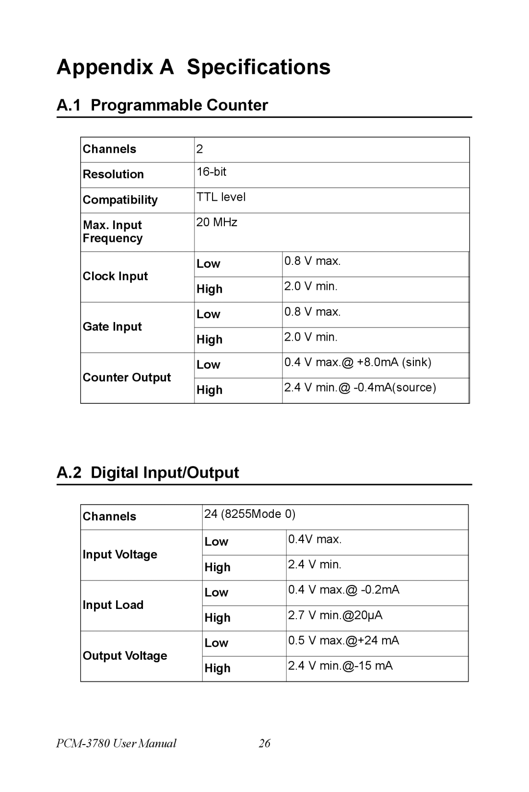
Channels | 2 |
|
| |
|
|
|
| |
Resolution |
|
| ||
|
|
|
| |
Compatibility | TTL level |
|
| |
|
|
|
| |
Max. Input | 20 MHz |
|
| |
Frequency |
|
|
| |
|
|
|
| |
Clock Input | Low | 0.8 | V max. | |
|
|
| ||
High | 2.0 | V min. | ||
| ||||
|
|
|
| |
Gate Input | Low | 0.8 | V max. | |
|
|
| ||
High | 2.0 | V min. | ||
| ||||
|
|
|
| |
Counter Output | Low | 0.4 | V max.@ +8.0mA (sink) | |
|
|
| ||
High | 2.4 | V min.@ | ||
| ||||
|
|
|
|
A.2 Digital Input/Output
Channels | 24 (8255Mode 0) | ||
|
|
| |
Input Voltage | Low | 0.4V max. | |
|
| ||
High | 2.4 V min. | ||
| |||
|
|
| |
Input Load | Low | 0.4 V max.@ | |
|
| ||
High | 2.7 V min.@20µA | ||
| |||
|
|
| |
Output Voltage | Low | 0.5 V max.@+24 mA | |
|
| ||
High | 2.4 V | ||
| |||
|
|
| |
26 |
