Protect PV.500_MH Operating Instructions
3.7Technology
Due to the utilisation of
The entire control electronics system for the equipment is based on the use of microcomputer assemblies. The fact that the various assemblies are logically integrated and linked into the overall sys- tem means that unit properties can be defined by making unit- specific parameter settings in the software.
Information is exchanged between the individual modules using the CAN bus (Controller Area Network). This CAN bus features high interference immunity and is used in a wide variety of indus- trial applications.
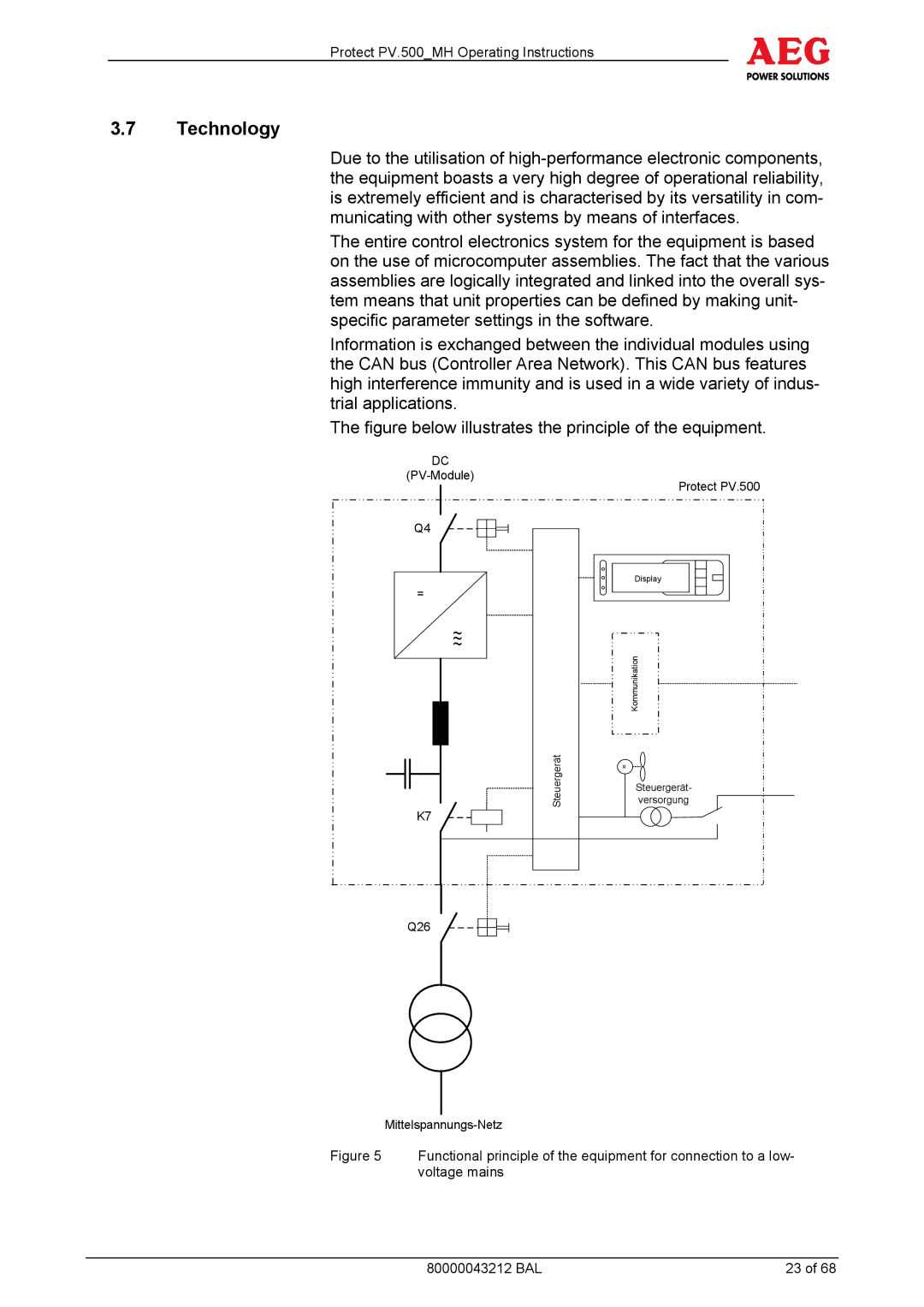
The figure below illustrates the principle of the equipment.
DC
Protect PV.500
Q4 |
|
| Display |
= |
|
~ |
|
~ | Kommunikation |
| |
Steuergerät | M |
Steuergerät- | |
versorgung | |
K7 |
|
Q26 |
|
Figure 5 Functional principle of the equipment for connection to a low- voltage mains
80000043212 BAL | 23 of 68 |