Protect PV.500_MH Operating Instructions
7.3Remote Signalling
The remote signalling board is a contact interface for signalling PV messages and controlling PV units. It is supplied as an option for the AEG PV system and is intended for installation in the PV unit. The remote signalling master board consists of 5
There is an independent 24 VDC power supply for the control in- put. The control signal is activated by bridging the relevant input. There is no need for an additional auxiliary power supply.
The signals are assigned as standard or can be configured on a
Technical data:
The maximum load for the signalling contacts (X3/X4) is 500 V/8 A
AC or 50 V/2 A DC.
i
If the specified power has been applied to the relay con- tacts once, those contacts can no longer reliably switch an
The control input (X5) has an independent 24 VDC power supply. The input is activated via a bridge.
Structure:
X2 1
S1
1
X7
1
1
1
X1
1 X6
OPT1 X51
K25 | X4 |
| 1 |
K24 |
|
| |
K23 | X3 |
K22 |
|
K21 |
|
| 1 |
2
1
3
2
1
12
11
10
9
8
7
6
5
4
3
2
1
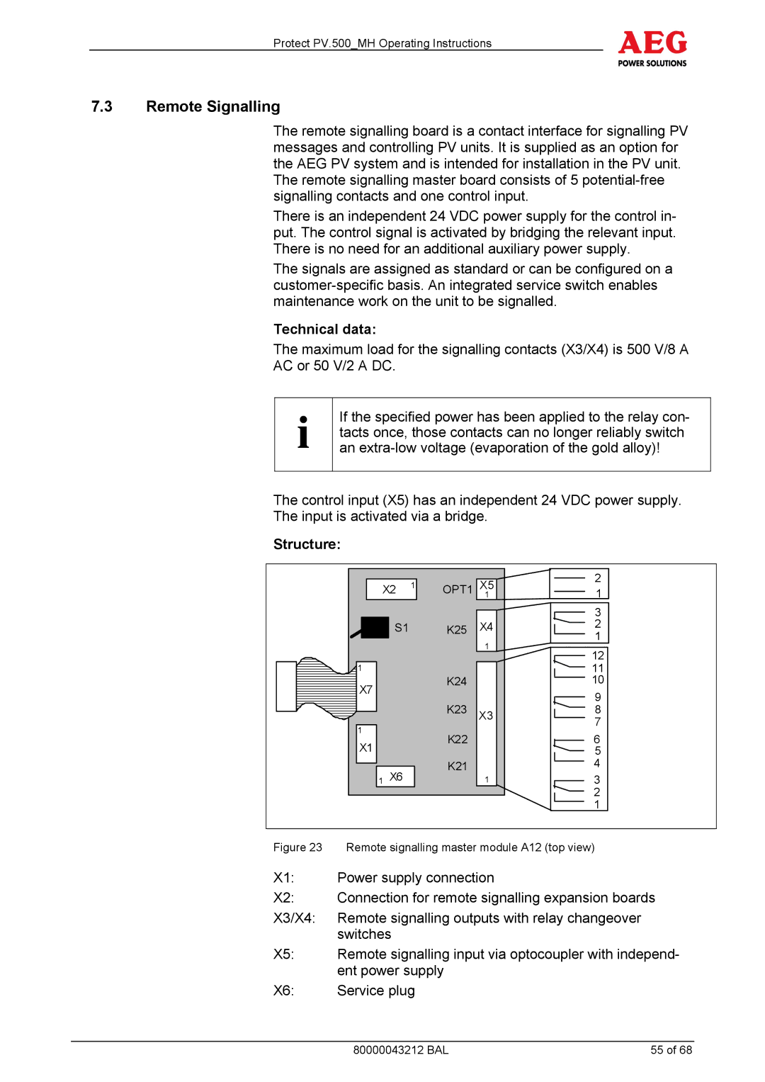
Figure 23 | Remote signalling master module A12 (top view) |
X1: | Power supply connection |
X2: | Connection for remote signalling expansion boards |
X3/X4: | Remote signalling outputs with relay changeover |
| switches |
X5: | Remote signalling input via optocoupler with independ- |
| ent power supply |
X6: | Service plug |
80000043212 BAL | 55 of 68 |