Protect PV.500_MH Operating Instructions
LED signals: |
|
Green/red flashes: | Configuration can be selected via the ter- |
| minal |
| (up to 30 seconds after restarting) |
Green on: | Operating status; no external communica- |
| tion via X2 and X5 |
Green flashes: | Data transmission on the serial interfaces |
| (X2 or X5) |
Red on: | Fault |
Description of serial interfaces:
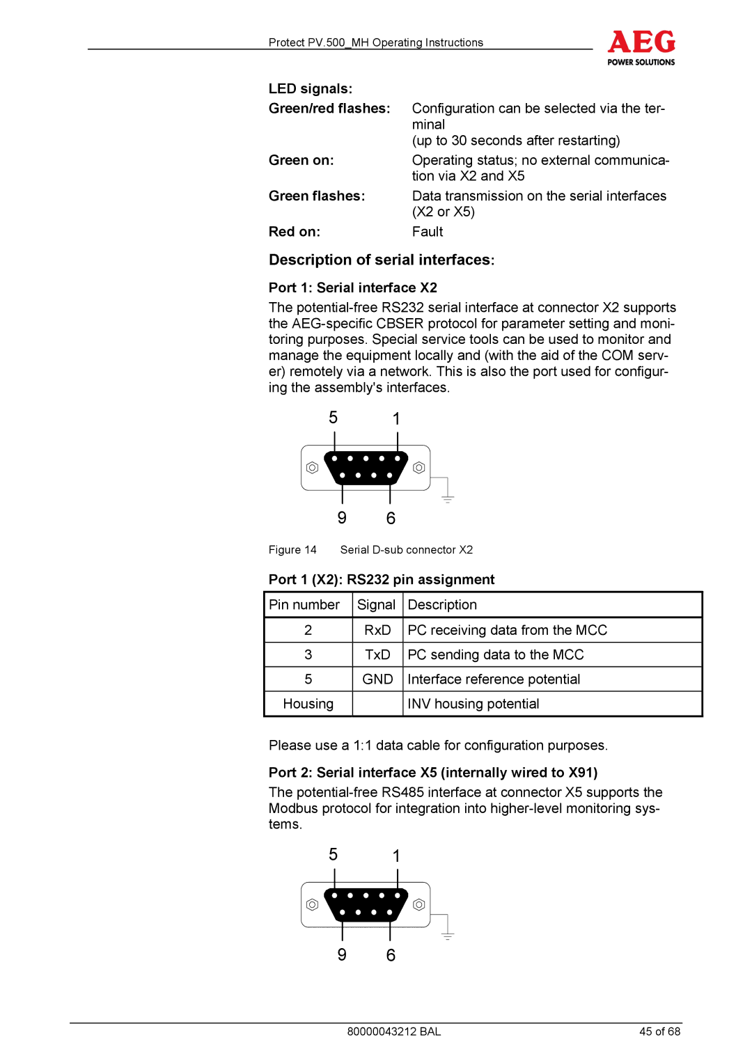
Port 1: Serial interface X2
The
5 1
9 | 6 |
|
Figure 14 Serial | ||
Port 1 (X2): RS232 pin assignment | ||
Pin number | Signal | Description |
|
|
|
2 | RxD | PC receiving data from the MCC |
|
|
|
3 | TxD | PC sending data to the MCC |
|
|
|
5 | GND | Interface reference potential |
|
|
|
Housing |
| INV housing potential |
|
|
|
Please use a 1:1 data cable for configuration purposes.
Port 2: Serial interface X5 (internally wired to X91)
The
51
9 6
80000043212 BAL | 45 of 68 |