Agilent 81101A 50 MHz Pulse Generator
Front Panel Display and Softkeys
Agilent 81101A 50 MHz Pulse Generator
Copyright
Limitation of Warranty
Safety Summary
Do Not Operate in an Explosive Atmosphere
Safety Symbols
About this Book
VOLTageHIGH
Contents
Contents
General Programming Aspects
GP-IB Interface Bus
Agilent 81101A Remote Control
SOURcePULSeDOUBle1STATe ONOFF. Sufficient to use
Programming Recommendations
DISPlay OFF
# switch off error check
# set default settings
# switch off display update
# enable the output
Common Command Summary
Command Parameter Description
Status Model
Event Register
Condition Register
Transition Filters
EVENt
Enable Register
Registers in Group Status Group CONDition
QUEStionable OPERation
Bit Description
Status Byte
Standard Event Status Group
Always
OPERation Status Group
This Status Group is not used in the instrument
QUEStionable Status Group
Bit QUEStionable
Programming Reference
Agilent 81101A Scpi Command Summary
See
High
DOUBle1 STATe
KEY
SET
Default Values, Standard Settings
Parameter RST, Default Values
Auto
KEY
LEVel SLOPe POSitive SOURce IMMediate
Programming the Instrument Trigger Modes
ARM Event detection layer
Gated
Continuous
Triggered
Burst
External Width
Pulses
Pulse period Source TRIGger SOURce
Scpi Instrument Command List
On OFF 1
Use the SOURceFREQuencyCWFIXed command
Armewid
Armfreq
Armimp
Armlev
Ns to 999.5 s
Armper
10.00 ∝s
Armsens
Frequency of the arming signal
Signal
Edge LEVel
Armsour
Disp
MMEMCAT?
Mmemcdir
Mmeminit
Mmemcopy
Mmemdel
Filename,A
Mmemloadstat
Mmemstorstat
OUTP1IMPEXT
To switch on the output
OUTP1IMP
50.0 Ω
CURR1
OUTP1POL
NORMal INVerted
OUTPutIMPedanceEXTernal
To program the amplitude current of the output signal
Offset
CURR1OFFSet
SOURceCURRent subsystem
CURR1HIGH
CURR1LOW
CURR1LIM
CURR1LIMLOW
CURR1LIMSTAT
Freq
Hold
Use this command to enable either of the SOURceVOLTage or
Freqauto
Voltage or current
With SOURcePULSeDELay
SOURcePULSeDELay1HOLD PRATio
001% to 99.9%, depends on width, transition & period
PULSDCYC1
10.0% derived from width and period
Period is varied rather than the absolute pulse width use
Time PRATio
SOURcePULSeDELay1HOLD Time
PULSDEL1HOLD
Parameter is programmed to a value without a unit suffix
To set the pulse delay to 50% of period
PULSDEL1UNIT
PULSDOUB1
PULSDOUB1DEL
SOURcePULSeDOUBle1DELayHOLD Time
To set and hold the double-pulse delay
TIMEPRATio
To set the double-pulse delay to 50%
PULSDOUB1DELHOLD
PULSDOUB1DELUNIT
PULSHOLD1
Pulsper
Pulsperauto
PULSTDEL1
PULSTRAN1HOLD
To program the pulse width by means of the delay parameters
When the pulse width is varied
Pulse width
PULSTRAN1UNIT
PULSTRAN1
PULSTRAN1TRA
To set the leading and trailing edges independently
PULSTRAN1TRAAUTO
PULSTRIG1VOLT
PULSWIDT1
Roscsour
MHz
To set up the external PLL reference
Roscextfreq
MHz or 10 MHz
Numeric Parameter suffix V with engineering prefixes
SOURceVOLTage subsystem
To +10
VOLT1OFFSet
With Amplitude, see
Specified current limits
500 mV
VOLT1HIGH
With low level, see
To 10.0 V 50 Ω into 50 Ω
To 9.9 V 50 Ω into 50 Ω
VOLT1LOW
With high level, see
To set the low level voltage
VOLT1LIM
VOLT1LIMLOW
To set and activate the high and low voltage limits
Command STATusOPERation
VOLT1LIMSTAT
Status Group Register
This command
Command STATusQUEStionable
PTR NTR
STATusQUEStionableCONDition?
STATusQUEStionableENABle
STATusQUEStionableEVENt?
STATusQUEStionableNTRansition
Systchec
SYSTERR?
Key Description
Systkey
No suffix allowed
No key pressed Query only
Cursor Up Cursor Down Cursor Left Cursor Right
Softkey
Command Systpres
Systsec
SYSTWARN?
Systset
SYSTVERS?
SYSTWARNBUFF?
SYSTWARNSTR?
Separator between the messages
TRIGCOUNt
Trigimp
Triggered by a positive edge at the EXT Input
EXT Input
50 Ω or 10 kΩ
Trigsour
Triglev
Trigslop
TRIGSOURce
Pulse period sources set by Trigsour
Pulse period source
IMMediate INTernal1
Scpi Instrument Command List
Used by the instrument
Temperature
Pulse Generator
Warranted Performance
Declaration of Conformity
Agilent 81112 a
Power requirements
Agilent 81101A Specifications
Safety
Maximum Dimensions H x W x D
Recalibration period
Weight
Warranty
Acoustic Noise Emission
Period can also be entered as frequency
Period
Glitch-free timing changes
Period Agilent 81101A
Width
Delay
Delay Agilent 81101A
Width Agilent 81101A
Transition Times
Double Pulse Delay
Double Pulse Delay Agilent 81101A
Transition Times Agilent 81101A
External Load compensation
Level Parameters Agilent 81101A
Pulse Performance
Level Specifications 50 Ω into 50 Ω 1k Ω into 50 Ω
Level Parameters
Pulse Performance Agilent 81101A
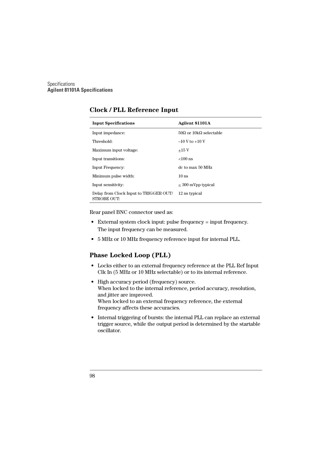
Clock / PLL Reference Input
Phase Locked Loop PLL
Input Specifications Agilent 81101A
External Clock
Pulses Mode
Burst Mode
Burst Parameters Agilent 81101A
Generate continuous pulses, double pulses, or bursts
Externally Triggered
Externally Gated
Trigger Output
Trigger Output Specifications Agilent 81101A
Strobe Output Specifications Agilent 81101A
Strobe Output
Typ
Typical Delays
Mode From Value
Non-Volatile Memory
Overprogramming
Help Key
Memory Card
Operates according to Ieee standard 488.2, 1987 and Scpi
Function Code
Programming Times
SH1, AH1, T6, L4, SR1, RL1, PP0, DC1, DT1,C0
Pulse Parameter Definitions
105
Pulse Period
Trigger Delay
Time Reference Point
Pulse Width
Interval between leading edge medians of the double pulses
Pulse Delay
Interchannel Delay Skew
108
Transition Time
Linearity
Pulse Levels
Jitter
Stability
109
110
Preshoot, Overshoot, Ringing
Settling Time
Repeatability
111
112
Burst
Symbols
113
Gated
Period
114
Jitter
Safety
115
116
Front Panel Controls
Page
Manual Changes
Model 81101A
Index of Manual Change Manual Frame Errata
Manual Change
Declaration of Conformity