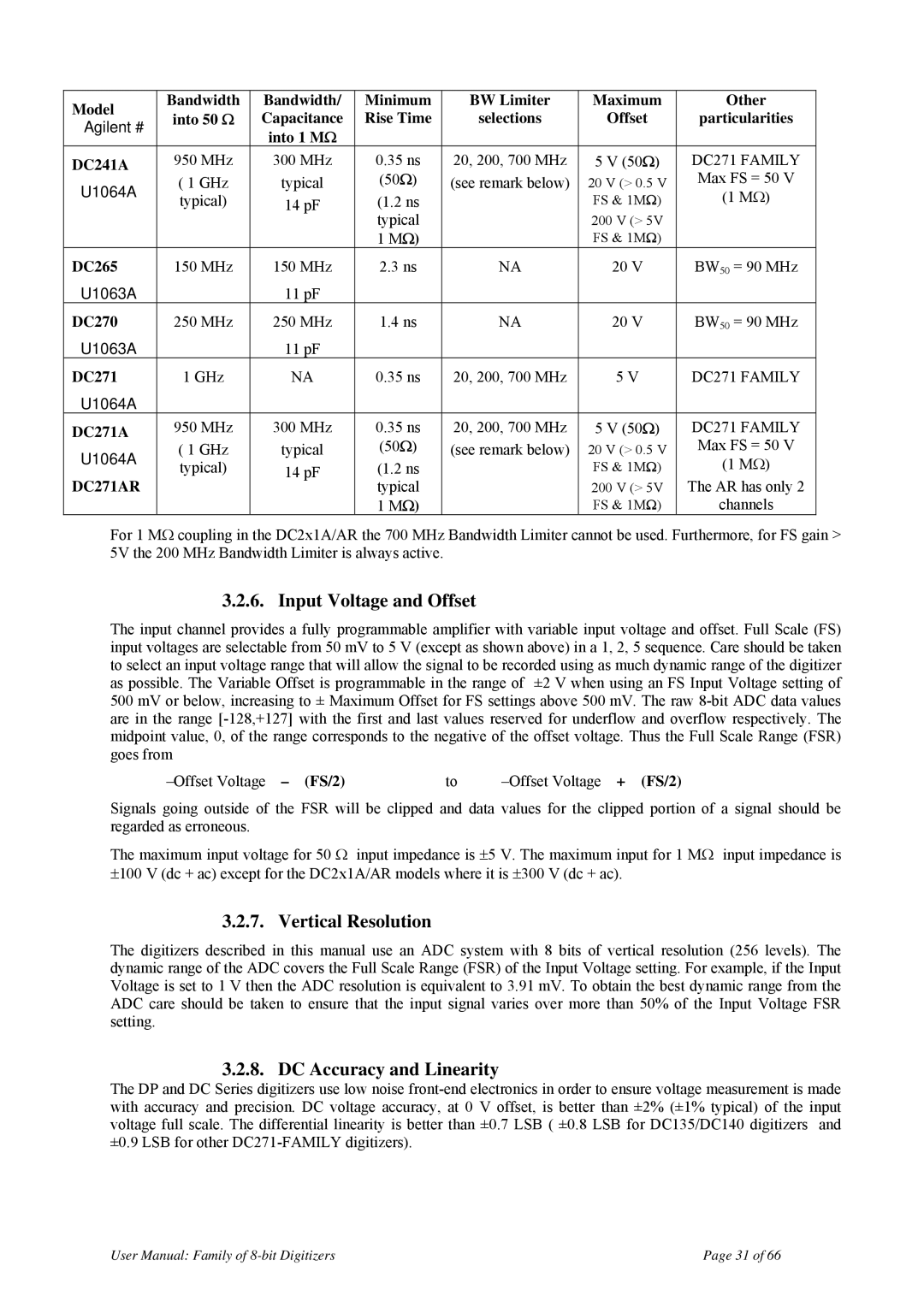
Model | Bandwidth | Bandwidth/ | Minimum | BW Limiter | Maximum | Other | |
into 50 Ω | Capacitance | Rise Time | selections | Offset | particularities | ||
Agilent # | |||||||
| into 1 MΩ |
|
|
|
| ||
|
|
|
|
|
| ||
DC241A | 950 MHz | 300 MHz | 0.35 ns | 20, 200, 700 MHz | 5 V (50Ω) | DC271 FAMILY | |
U1064A | ( 1 GHz | typical | (50Ω) | (see remark below) | 20 V (> 0.5 V | Max FS = 50 V | |
typical) | 14 pF | (1.2 ns |
| FS & 1MΩ) | (1 MΩ) | ||
|
| ||||||
|
|
| typical |
| 200 V (> 5V |
| |
|
|
| 1 MΩ) |
| FS & 1MΩ) |
| |
DC265 | 150 MHz | 150 MHz | 2.3 ns | NA | 20 V | BW50 = 90 MHz | |
U1063A |
| 11 pF |
|
|
|
| |
DC270 | 250 MHz | 250 MHz | 1.4 ns | NA | 20 V | BW50 = 90 MHz | |
U1063A |
| 11 pF |
|
|
|
| |
DC271 | 1 GHz | NA | 0.35 ns | 20, 200, 700 MHz | 5 V | DC271 FAMILY | |
U1064A |
|
|
|
|
|
| |
DC271A | 950 MHz | 300 MHz | 0.35 ns | 20, 200, 700 MHz | 5 V (50Ω) | DC271 FAMILY | |
U1064A | ( 1 GHz | typical | (50Ω) | (see remark below) | 20 V (> 0.5 V | Max FS = 50 V | |
typical) | 14 pF | (1.2 ns |
| FS & 1MΩ) | (1 MΩ) | ||
DC271AR |
| ||||||
|
| typical |
| 200 V (> 5V | The AR has only 2 | ||
|
|
| 1 MΩ) |
| FS & 1MΩ) | channels |
For 1 MΩ coupling in the DC2x1A/AR the 700 MHz Bandwidth Limiter cannot be used. Furthermore, for FS gain > 5V the 200 MHz Bandwidth Limiter is always active.
3.2.6. Input Voltage and Offset
The input channel provides a fully programmable amplifier with variable input voltage and offset. Full Scale (FS) input voltages are selectable from 50 mV to 5 V (except as shown above) in a 1, 2, 5 sequence. Care should be taken to select an input voltage range that will allow the signal to be recorded using as much dynamic range of the digitizer as possible. The Variable Offset is programmable in the range of ±2 V when using an FS Input Voltage setting of 500 mV or below, increasing to ± Maximum Offset for FS settings above 500 mV. The raw
to |
Signals going outside of the FSR will be clipped and data values for the clipped portion of a signal should be regarded as erroneous.
The maximum input voltage for 50 Ω input impedance is ±5 V. The maximum input for 1 MΩ input impedance is
±100 V (dc + ac) except for the DC2x1A/AR models where it is ±300 V (dc + ac).
3.2.7. Vertical Resolution
The digitizers described in this manual use an ADC system with 8 bits of vertical resolution (256 levels). The dynamic range of the ADC covers the Full Scale Range (FSR) of the Input Voltage setting. For example, if the Input Voltage is set to 1 V then the ADC resolution is equivalent to 3.91 mV. To obtain the best dynamic range from the ADC care should be taken to ensure that the input signal varies over more than 50% of the Input Voltage FSR setting.
3.2.8. DC Accuracy and Linearity
The DP and DC Series digitizers use low noise
User Manual: Family of | Page 31 of 66 |