will be in the range [0 V, 0.7 V] and the high level in the range [1.7 V, 3.3 V] for HiZ. The high level output will typically give 0.8 V into 50 Ω. The I/O A or B connectors can be used for an Enable trigger input or the following output signals: 10 MHz reference clock, Acquisition skipping to next segment, Acquisition is active, Trigger is armed.
3.9.External Trigger Output (DP1400 & DC271-FAMILY)
When the digitizer is ready to be triggered and a valid trigger signal occurs, a trigger output is generated for external use. It is always available on the Front Panel Trigger Out MCX or MMCX connector. The pulse ends when the data acquisition for the trigger in question is complete.
NOTE: The External Trigger Output functionality is implemented in the hardware. No Trigger Out signal occurs for
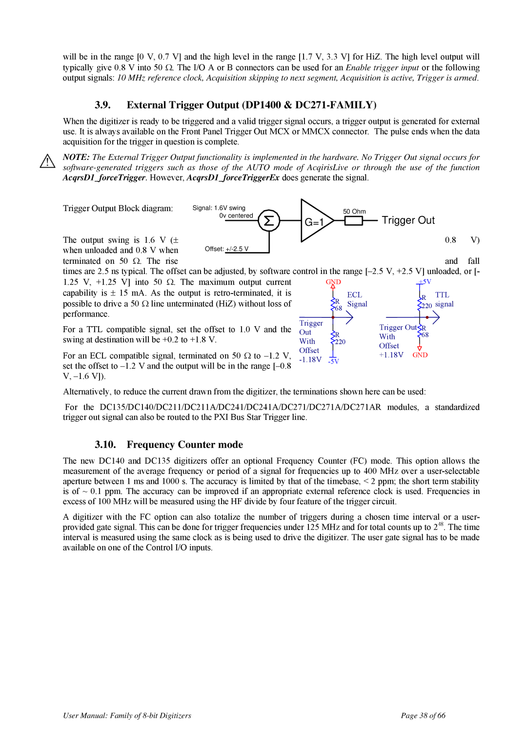
Trigger Output Block diagram: | Signal: 1.6V swing |
|
| 50 Ohm |
| |||
| 0v centered |
| G=1 |
|
|
| Trigger Out |
|
|
|
|
|
|
| |||
|
|
|
|
|
|
| ||
|
|
|
|
|
| |||
The output swing is 1.6 V (± |
|
|
| 0.8 | V) | |||
when unloaded and 0.8 V when | Offset: |
|
|
|
|
| and | fall |
terminated on 50 Ω. The rise |
|
|
|
|
|
| ||
times are 2.5 ns typical. The offset can be adjusted, by software control in the range
1.25 V, +1.25 V] into 50 Ω. The maximum output current |
| GND |
|
| +5V |
| ||
|
|
|
|
|
| |||
capability is ± 15 mA. As the output is |
|
| R | ECL |
| R | TTL | |
|
|
| ||||||
|
|
| ||||||
possible to drive a 50 Ω line unterminated (HiZ) without loss of |
|
| Signal |
| signal | |||
|
|
| 220 | |||||
performance. |
| 68 |
|
|
| |||
For a TTL compatible signal, set the offset to 1.0 V and the | Trigger |
|
|
| Trigger Out R |
| ||
Out |
|
|
|
| ||||
| R |
| With | 68 |
| |||
swing at destination will be +0.2 to +1.8 V. | With | 220 |
|
|
|
| ||
| Offset |
|
|
| Offset |
|
|
|
For an ECL compatible signal, terminated on 50 Ω to |
|
|
| +1.18V GND |
| |||
|
|
|
| |||||
|
| |||||||
|
|
|
|
| ||||
set the offset to |
|
|
|
|
|
|
|
|
V,
Alternatively, to reduce the current drawn from the digitizer, the terminations shown here can be used:
For the DC135/DC140/DC211/DC211A/DC241/DC241A/DC271/DC271A/DC271AR modules, a standardized trigger out signal can also be routed to the PXI Bus Star Trigger line.
3.10.Frequency Counter mode
The new DC140 and DC135 digitizers offer an optional Frequency Counter (FC) mode. This option allows the measurement of the average frequency or period of a signal for frequencies up to 400 MHz over a
A digitizer with the FC option can also totalize the number of triggers during a chosen time interval or a user- provided gate signal. This can be done for trigger frequencies under 125 MHz and for total counts up to 248. The time interval is measured using the same clock as is being used to drive the digitizer. The user gate signal has to be made available on one of the Control I/O inputs.
User Manual: Family of | Page 38 of 66 |