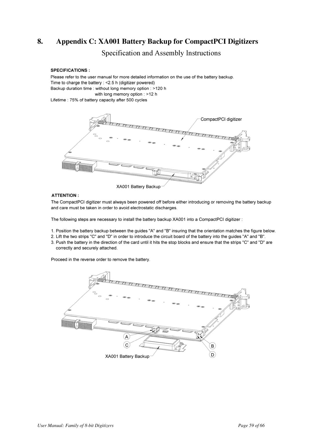
DP105 / DP106 / DP110 DP111 / DP210 / DP211 / DP212
AGILENT ACQIRIS USER MANUAL FAMILY OF 8-BIT DIGITIZERS
XZ001
For Use with DP and DC Series Digitizers Models covered
Acqiris Headquarters
3. PRODUCT DESCRIPTION
CONTENTS
2. INSTALLATION
1. OUT OF THE BOX
4. RUNNING THE ACQIRISLIVE APPLICATION
1.3. Conventions Used in This Manual
1.2. Using this Manual
1. Out of the Box
1.1. Message to the User
1.6. Packaging and Handling
1.4. Disclaimer and Safety
1.5. Warning Regarding Medical Use
1.9. System Requirements
1.7. Warranty
1.8. Warranty and Repair Return Procedure, Assistance and Support
Step
1.11. Maintenance
1.10. Transport & Shipping
Hard Drive Space 20 MB Minimum
1.13. Disposal and Recycling
1.12. Cleaning
2.1.2. IC414 Windows software installation
2. Installation
2.1. IC414 Installation
2.1.1. IC414 Hardware installation hints
2.2.2. Multiple Versions
2.2. Installing the Software under Windows 2.2.1. Warnings
2.2.3. Installation
3. To proceed with the installation click “Next”. The following screen will be shown
5. Pick the desired combination of module families and click Next to continue
8. The screen below asks for the desired installation type. After having made your choice Click “Next” to continue
10. If MATLAB is installed on your machine, you will be asked to point the installer to the MATLAB root directory. You should do this if you want the installer to modify the standard startup.m file to incorporate the Acqiris adaptor
13. If you have enabled the installation of 12-bit Digitizers, Averagers, or Analyzers, the next screen lets you change the name of the directory where the FPGA firmware will be installed
15. Depending on the install type, you may be asked which LabVIEW version format you want for the LabVIEW files. Select the appropriate format and click “Next” to continue
17. You are now ready to install. You may still go back to any previous screen to modify your selection. Click “Install” when ready
Page 19 of
User Manual Family of 8-bit Digitizers
21. Click “Finish”. The software installation is now complete
2.3. Installing the Software for Linux
cd linux2.6driverpci
2.3.1. Kernel Mode Driver Compilation
cd linuxdriverpci
fpgaPath=/usr/local/AcqirisLinux/Firmware
2.4. Installing the Hardware
2.3.2. Special cases
2.3.3. Environment variables for the Firmware
2.5.2. Windows XP
2.5. After Restarting 2.5.1. Windows
Page 25 of
To proceed with the installation click “Next”. You should then see
User Manual Family of 8-bit Digitizers
2.6. LabVIEW RT
2.8. Distribution for Windows 2000/XP and Linux
2.7. Installing the IVI-COM/C Driver
3.1. Overview
DP110 Block Diagram
3. Product Description
3.2.4. Mezzanine Front-end
3.2. Channel Input 3.2.1. Coupling
3.2.2. Impedance
3.2.3. Input Protection
selections
3.2.8. DC Accuracy and Linearity
3.2.7. Vertical Resolution
3.2.6. Input Voltage and Offset
DC271AR
3.2.9. Using Probes
3.3. Data Acquisition
3.3.3. Single and Sequence Acquisition Modes
3.3.1. Sampling Rate
3.3.2. Acquisition Memory
3.3.7. Combining channels
3.3.4. DP1400 Simultaneous Multibuffer Acquisition and Readout SMAR
3.3.5. Timing
3.3.6. Timebase Range
3.4.5. Window Trigger
3.4.2. Trigger Coupling
3.4.3. Trigger Level
3.4.4. Edge Trigger Slope
3.5. External Clock and Reference
3.4.9. Pre- and Post-Trigger Delay
3.4.10. Trigger Status
Connector
3.6. Internal Calibration
3.7. ASBus
3.8. Special Front Panel Input and OutputDP1400 & DC271-FAMILY
Trigger Out
3.9. External Trigger Output DP1400 & DC271-FAMILY
3.10. Frequency Counter mode
Page
Operating Temperature
Dimensions
Safety
3.11.2. Environmental and Physical
4.1. Getting Started with AcqirisLive
4. Running the AcqirisLive Application
DSO TR
4.2. Control Panel and Functions
4.2.1. Control Panel Mode
Oscilloscope Mode
4.2.2. Displaying Multiple Traces
4.2.5. Input Voltage Scale, Offset and Coupling
4.2.3. Numeric Editor
4.2.4. Keyboard shortcuts
4.2.7. Acquisition Mode
4.2.6. Trigger
4.2.8. Timebase and Memory
4.2.9. Using digitizers of different models simultaneously
4.2.10. Segmented Memory
4.2.11. Display Features, Zoom and Persistence
4.5. Store, Autostore and Conversion of Waveforms
4.4. Setup
4.3. Top Line Menu of AcqirisLive
data and an additional ASCII format
4.9. Additional Waveform Information
4.6. Calibrate
4.7. Combine channels
4.8. External 10 MHz Reference and External Clock
Syntax
4.10. Display Features
4.11. Command Line Switches
Available Switches
DMA Data Transfers
Buffer size
Banks for SMAR
Calibration
Multi-instruments
Temperature Update
Simulation Mode
Acquisition State
5.1. Who needs a Geographical Map of Modules
5.2. When should the GeoMapper Application be used
5.3. How to run GeoMapper
5. Running the GeoMapper Application
correspond to your expectations you may have hardware problems unpowered, broken, or badly cabled crates or modules
The final step is to actuate the Save button so that the final configuration will be memorized and made available to the driver
Page 57 of
User Manual Family of 8-bit Digitizers
Page 58 of
7. Appendix B ASBus2 for PCI Digitizers
User Manual Family of 8-bit Digitizers
Page 59 of
User Manual Family of 8-bit Digitizers
Page 60 of
User Manual Family of 8-bit Digitizers
Page 61 of
User Manual Family of 8-bit Digitizers
Page 62 of
User Manual Family of 8-bit Digitizers
Page 63 of
User Manual Family of 8-bit Digitizers
Page 64 of
13. Appendix H XP104 Fan Unit for DP1400
User Manual Family of 8-bit Digitizers
Page 65 of
User Manual Family of 8-bit Digitizers
Page 66 of
14. Appendix I XP105 Fan Unit for DP1400
User Manual Family of 8-bit Digitizers