Manuals
/
Agilent Technologies
/
Computer Equipment
/
Graphics Tablet
Agilent Technologies
DP240, DP212, DP214, DP110, DP111, DP210 Appendix H XP104 Fan Unit for DP1400
Models:
DC140
DC110
DC211
DC135
DP105
DP106
DP211
DP235
DP210
DP111
DP1400
DP110
DP214
DP212
DP240
1
64
66
66
Download
66 pages
37.45 Kb
59
60
61
62
63
64
65
66
Install
DP110 Block Diagram
Pre- and Post-Trigger Delay
Warranty
Dimension
Maintenance
Setup
Command Line Switches
Cleaning
Resolution
Page 64
Image 64
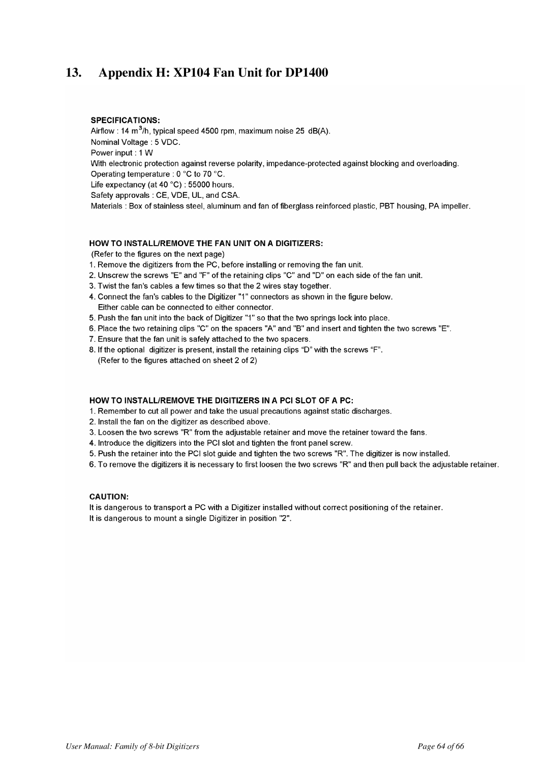
13.
Appendix H: XP104 Fan Unit for DP1400
User Manual: Family of
8-bit
Digitizers
Page 64 of 66
Page 63
Page 65
Page 64
Image 64
Page 63
Page 65
Contents
Agilent Acqiris Family BIT Digitizers
XZ001
USA
Contents OUT of the BOX
Running the Acqirislive Application
Message to the User
Using this Manual
Conventions Used in This Manual
Disclaimer and Safety
Packaging and Handling
Warranty
System Requirements
Maintenance
Transport & Shipping
Cleaning
Disposal and Recycling
IC414 Installation 1. IC414 Hardware installation hints
2. IC414 Windows software installation
Installation
Installing the Software under Windows
Multiple Versions
Page
Page
Page
Page
Page
Page
Page
Page
Page
Installing the Software for Linux
Kernel Mode Driver Compilation
ƒ cd linuxdriverpci
Special cases
Installing the Hardware
Environment variables for the Firmware
After Restarting Windows
Windows XP
Page
LabVIEW RT
Installing the IVI-COM/C Driver
Distribution for Windows 2000/XP and Linux
DP110 Block Diagram
Overview
Channel Input Coupling
Impedance
Input Protection
Mezzanine Front-end
Offset Particularities
Input Voltage and Offset
Vertical Resolution
DC Accuracy and Linearity
Using Probes
Data Acquisition
Acquisition Memory
Sampling Rate
Single and Sequence Acquisition Modes
Timing
Timebase Range
Combining channels
Trigger
Trigger Coupling
Trigger Level
Edge Trigger Slope
Window Trigger
Trigger Status
Pre- and Post-Trigger Delay
External Clock and Reference
ASBus
Internal Calibration
Special Front Panel Input and OutputDP1400 & DC271-FAMILY
Frequency Counter mode
External Trigger Output DP1400 & DC271-FAMILY
PCI DMA
Operating Temperature
Dimensions
Safety
Environmental and Physical
Running the AcqirisLive Application
Getting Started with AcqirisLive
Control Panel Mode
Control Panel and Functions
Displaying Multiple Traces
Keyboard shortcuts
Numeric Editor
Input Voltage Scale, Offset and Coupling
Acquisition Mode
Using digitizers of different models simultaneously
Timebase and Memory
Display Features, Zoom and Persistence
Segmented Memory
Top Line Menu of AcqirisLive
Setup
Store, Autostore and Conversion of Waveforms
Page
Calibrate
Combine channels
External 10 MHz Reference and External Clock
Additional Waveform Information
Display Features
Command Line Switches
Available Switches
Operation Mode
Transient Recorder mode
Buffer size
Banks for Smar
Calibration
Simulation Mode
Temperature Update
Acquisition State
Multi-instruments
How to run GeoMapper
When should the GeoMapper Application be used
Who needs a Geographical Map of Modules
Page
Page
Page
Appendix B ASBus2 for PCI Digitizers
Page
Page
Page
Page
Page
Appendix H XP104 Fan Unit for DP1400
Page
Appendix I XP105 Fan Unit for DP1400
Top
Page
Image
Contents