1.Clicking on the white numeric display of the voltage scale will show a
2.Clicking on the Decrement / Increment icons will step the voltage scale up or down to the next level for each click of the mouse.
3.Clicking Max / Min will toggle to the least sensitive gain setting or to the most sensitive gain setting.
The input Coupling can be set for AC or DC. The selected setting is shown as an actuated indicator with a green backlight. AC coupling blocks DC signal components from the input. The AC coupling mode acts as a high pass filter passing frequencies above 10 Hz. In DC coupling all frequency components are passed through the input.
The input voltage offset control applies an offset to the input amplifier in order to better digitize and display signals offset away from 0 volts. Signals riding on a DC level can be most accurately characterized when the offset is adjusted so that the acquisitions are made about the midpoint of the digitizer’s Full Scale Range, and when as much of the
The Impedance selection allows the user to choose the appropriate internal input termination of 50 Ω or 1 MΩ. The Adv button in this section gives access to the choice of hardware bandwidth limits for the channel.
4.2.6. Trigger
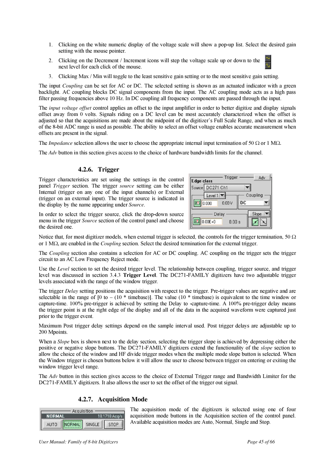
Trigger characteristics are set using the settings in the control panel Trigger section. The trigger source setting can be either Internal (trigger on any one of the input channels) or External (trigger on an external input). The trigger source is indicated in the display by the name appearing under Source.
In order to select the trigger source, click the
Notice that, for most digitizer models, when external trigger is selected, the controls for the trigger termination, 50 Ω or 1 MΩ, are enabled in the Coupling section. Select the desired termination for the external trigger.
The Coupling section also contains a selection for AC or DC coupling. AC coupling on the trigger sets the trigger circuit to an AC Low Frequency Reject mode.
Use the Level section to set the desired trigger level. The relationship between coupling, trigger source, and trigger level was discussed in section 3.4.3 Trigger Level. The
The trigger Delay setting positions the acquisition with respect to the trigger.
Maximum Post trigger delay settings depend on the sample interval used. Post trigger delays are adjustable up to 200 Mpoints.
When a Slope box is shown next to the delay section, selecting the trigger slope is achieved by depressing either the positive or negative slope buttons. The
The Adv button in this section gives access to the choice of External Trigger range and Bandwidth Limiter for the
4.2.7. Acquisition Mode
The acquisition mode of the digitizers is selected using one of four acquisition mode buttons in the Acquisition section of the control panel. Available acquisition modes are Auto, Normal, Single and Stop.
User Manual: Family of | Page 45 of 66 |