3.6.Internal Calibration
The software drivers supplied include calibration functions for the timing, gain and offset settings, which can be executed upon user request. The digitizers are never calibrated in an “automatic” way, i.e. as a side effect of another operation. This ensures programmers have full control of all calibrations performed through software in order to maintain proper event synchronization within automated test applications.
The model DC and DP series digitizers include a high precision voltage source and a
For accurate time and voltage measurements it is recommended to perform a calibration once the module has attained a stable operating temperature (usually reached with a few minutes of digitizer operation after power on). Further calibration should not be necessary unless temperature variations occur.
A full internal calibration of a digitizer can be very time consuming (> 100 s/digitizer), in particular for the DC2x1A models. Therefore, several other options are available. They are documented in the Programmer's Reference Manual. A program can always be started with the digitizer in an uncalibrated state and data taken can be used for many kinds of testing. However, as soon as good data respecting the specifications of the instrument is required a calibration of at least the current acquisition state is needed. The full internal calibration has the advantage that it generates the calibration constants needed for any possible configuration of the instrument; its disadvantage is the time taken. If a more selective calibration is done it will allow the generation of good data in the current acquisition state. This calibration will remain useable whenever that acquisition state is used again for as long as the temperature of the instrument does not change significantly. A fast calibration of a channel in a configuration can be done in around a second. Many applications can save time by only performing calibration for the configurations that will actually be used.
3.7.ASBus
The DC Series digitizers may be used in applications that require many data acquisition channels. In such cases it is possible to use more than one digitizer in a standard CompactPCI/PXI crate. Each DC Series digitizer, except the DC135 and DC140 models, includes ASBus, a proprietary high bandwidth
The ASBus distributes both the clock and trigger signals along a
The ASBus is intended to connect modules of the same type, i.e. of the same model number, although some exceptions to this rule might be possible. If modules with the same model number, but different memory length options, are connected only the shortest memory length can be used.
The ASBus connector is located on the front panel of each cPCI module. Bridges are used to connect adjacent modules for synchronization, which is then activated through software by defining a master module and the trigger source. Up to 7 modules may be synchronized with the ASBus. More detailed information and the commands required to setup the ASBus clock and trigger distribution are included in the Programmer's Guide and Reference manual.
The DP1400 uses the ASBus2 system with a connector on the top of each card to achieve the same functionality. It works for up to 3 modules.
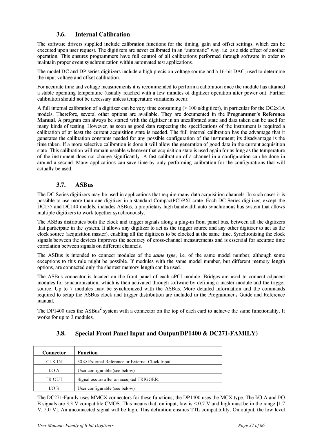
3.8.Special Front Panel Input and Output(DP1400 & DC271-FAMILY)
Connector | Function |
CLK IN | 50 Ω External Reference or External Clock Input |
I/O A | User configurable (see below) |
TR OUT | Signal occurs after an accepted TRIGGER. |
I/O B | User configurable (see below) |
The
User Manual: Family of | Page 37 of 66 |