Creating Multiple Multiplexers
Channel
(BB)0
(BB)1
(BB)2
(BB)0
(BB)1
(BB)2
(BB+1)0
(BB+1)1
(BB+1)2
(BB+2)0
(BB+2)1
(BB+2)2
You can configure the Cascade RF Switch module to create multiple multiplexers of varying sizes. In its
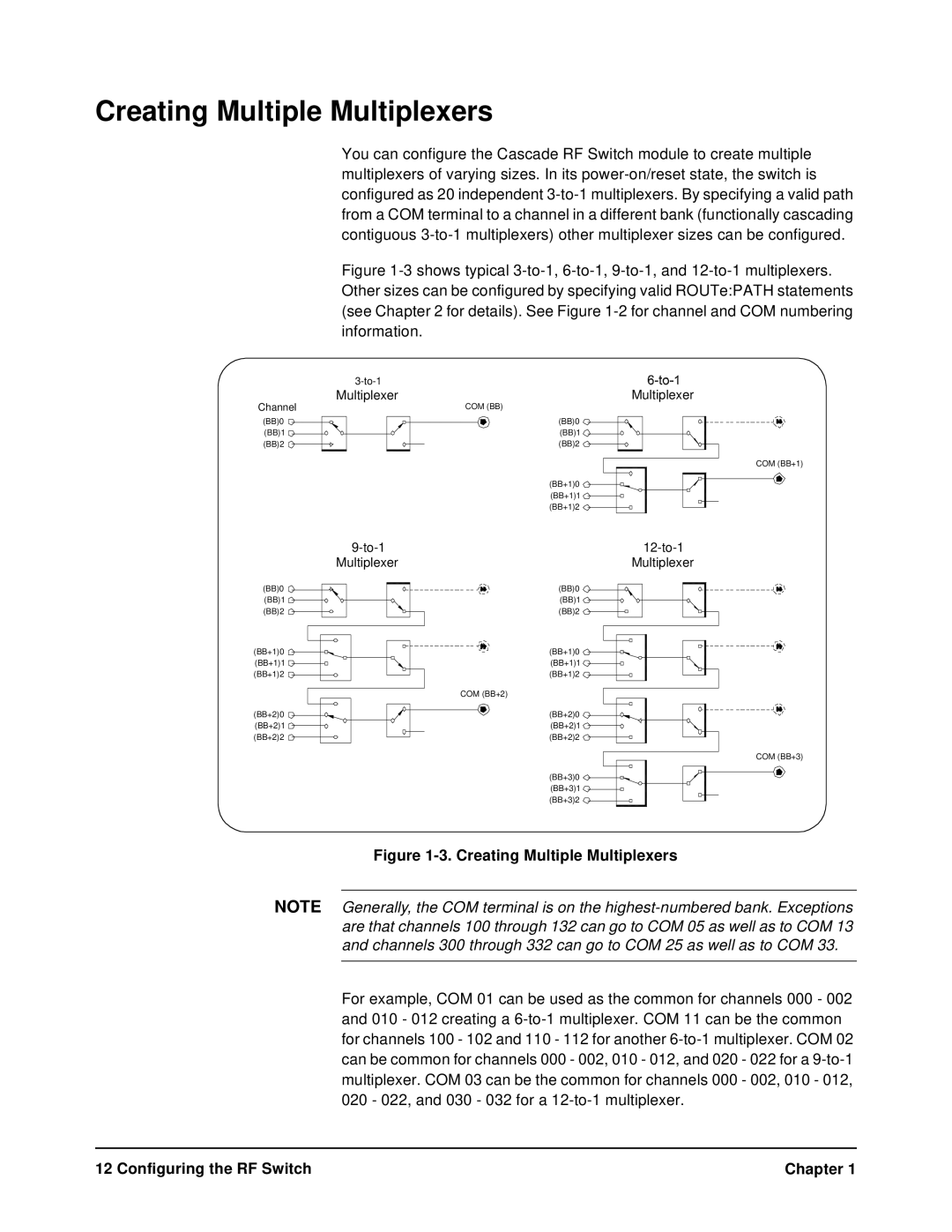
Figure 1-3 shows typical 3-to-1, 6-to-1, 9-to-1, and 12-to-1 multiplexers. Other sizes can be configured by specifying valid ROUTe:PATH statements (see Chapter 2 for details). See Figure 1-2 for channel and COM numbering information.
|
| ||
Multiplexer | |||
Multiplexer | |||
| COM (BB) | ||
(BB)0
(BB)1
(BB)2
COM (BB+1)
(BB+1)0
(BB+1)1
(BB+1)2
Multiplexer | Multiplexer |
(BB)0
(BB)1
(BB)2
(BB+1)0
(BB+1)1
(BB+1)2
COM (BB+2)
(BB+2)0
(BB+2)1
(BB+2)2
COM (BB+3)
(BB+3)0
(BB+3)1
(BB+3)2
Figure 1-3. Creating Multiple Multiplexers
NOTE Generally, the COM terminal is on the
For example, COM 01 can be used as the common for channels 000 - 002 and 010 - 012 creating a
12 Configuring the RF Switch | Chapter 1 |