Setting the Logical Address
NOTE
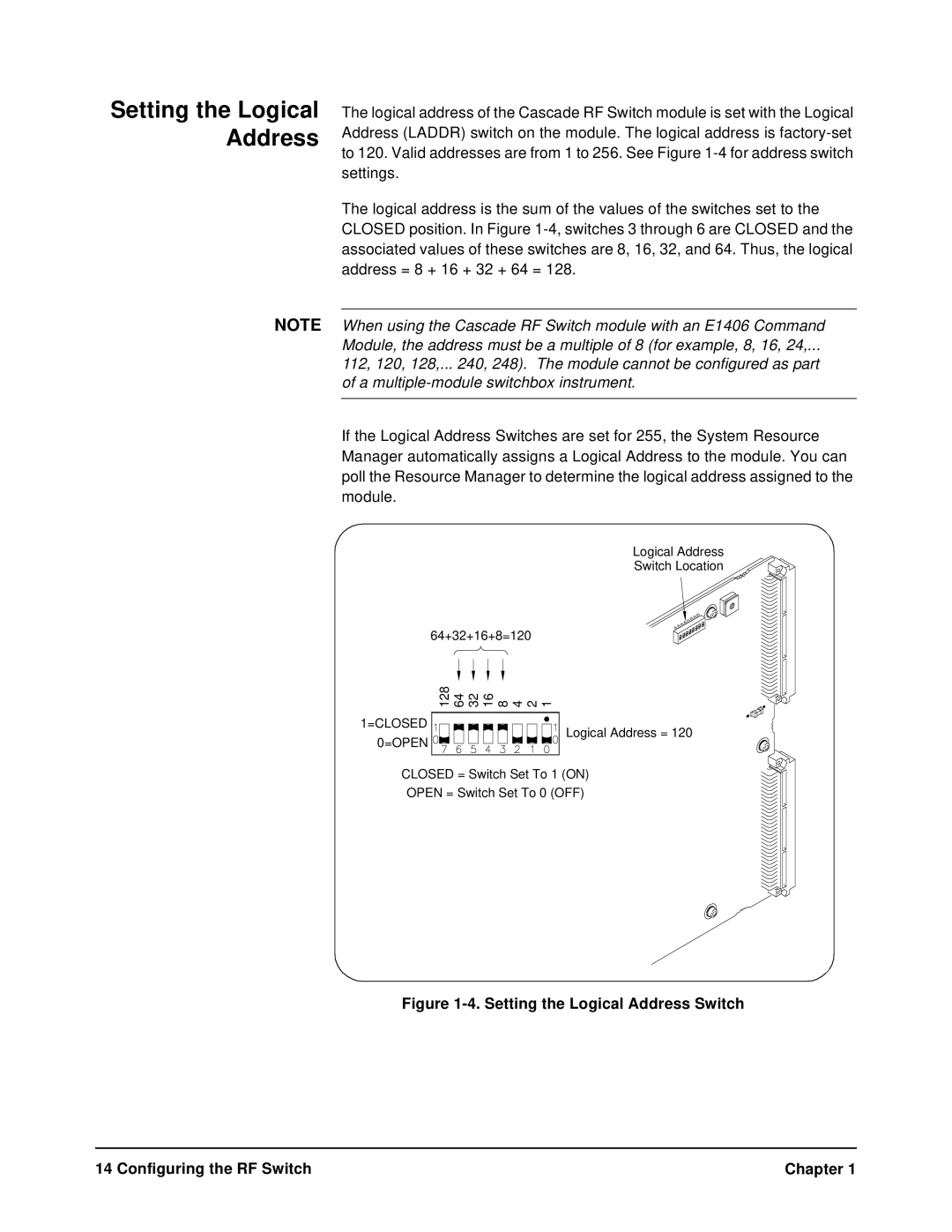
The logical address of the Cascade RF Switch module is set with the Logical Address (LADDR) switch on the module. The logical address is
The logical address is the sum of the values of the switches set to the CLOSED position. In Figure
When using the Cascade RF Switch module with an E1406 Command Module, the address must be a multiple of 8 (for example, 8, 16, 24,...
112, 120, 128,... 240, 248). The module cannot be configured as part of a
If the Logical Address Switches are set for 255, the System Resource Manager automatically assigns a Logical Address to the module. You can poll the Resource Manager to determine the logical address assigned to the module.
Logical Address
Switch Location
64+32+16+8=120
128 64 32 16 8 4 2 1
1=CLOSED
0=OPEN
Logical Address = 120
CLOSED = Switch Set To 1 (ON)
OPEN = Switch Set To 0 (OFF)
Figure 1-4. Setting the Logical Address Switch
14 Configuring the RF Switch | Chapter 1 |
