Chapter 1
Configuring the RF Switch
Using This Chapter
This chapter gives guidelines to use the Cascade RF Switch module (RF Switch) including:
• Switching Diagram . . . . . . . . . . . . . . . . . . . . . . . . . . . . . . . . . . .9
• Creating Multiple Multiplexers. . . . . . . . . . . . . . . . . . . . . . . . . .12
• RF Switch Configuration . . . . . . . . . . . . . . . . . . . . . . . . . . . . . .14
Switching Diagram
The E1470A Cascade RF Switch module consists of a series of twenty
Multiple combinations are simultaneously allowed on the module.
User connections to the module are to SMB connectors on the faceplate. Figure
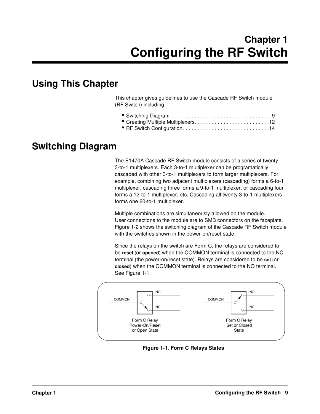
Since the relays on the switch are Form C, the relays are considered to be reset (or opened) when the COMMON terminal is connected to the NC terminal (the
NO
COMMON | COMMON |
|
|
NC
NO
NC
Form C Relay | Form C Relay |
Set or Closed | |
or Open State | State |
Figure 1-1. Form C Relays States
Chapter 1 | Configuring the RF Switch 9 |