A16 Address Space
Outside the Command
Module
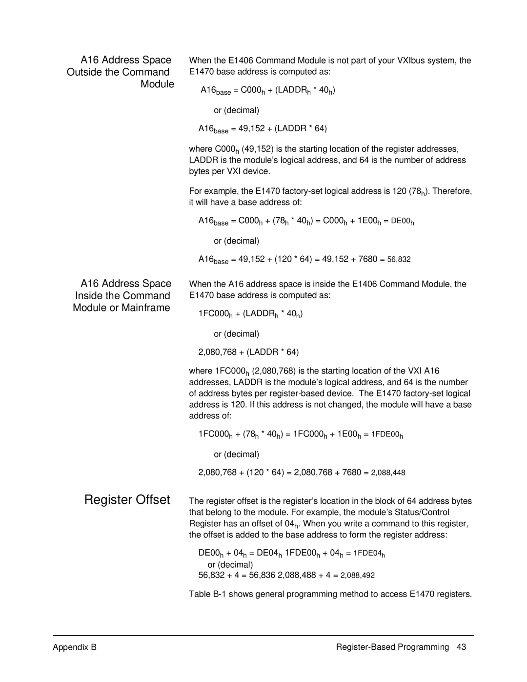
When the E1406 Command Module is not part of your VXIbus system, the
E1470 base address is computed as:
A16base = C000h + (LADDRh * 40h)
or (decimal)
A16base = 49,152 + (LADDR * 64)
A16 Address Space Inside the Command Module or Mainframe
where C000h (49,152) is the starting location of the register addresses, LADDR is the module’s logical address, and 64 is the number of address bytes per VXI device.
For example, the E1470
A16base = C000h + (78h * 40h) = C000h + 1E00h = DE00h
or (decimal)
A16base = 49,152 + (120 * 64) = 49,152 + 7680 = 56,832
When the A16 address space is inside the E1406 Command Module, the
E1470 base address is computed as:
1FC000h + (LADDRh * 40h)
or (decimal)
2,080,768 + (LADDR * 64)
where 1FC000h (2,080,768) is the starting location of the VXI A16 addresses, LADDR is the module’s logical address, and 64 is the number of address bytes per
1FC000h + (78h * 40h) = 1FC000h + 1E00h = 1FDE00h
or (decimal)
2,080,768 + (120 * 64) = 2,080,768 + 7680 = 2,088,448
Register Offset The register offset is the register’s location in the block of 64 address bytes that belong to the module. For example, the module’s Status/Control Register has an offset of 04h. When you write a command to this register, the offset is added to the base address to form the register address:
DE00h + 04h = DE04h 1FDE00h + 04h = 1FDE04h or (decimal)
56,832 + 4 = 56,836 2,088,488 + 4 = 2,088,492
Table
Appendix B |
