ASSEMBLY
Using the wire identified as
ELECTRICAL CIRCUIT
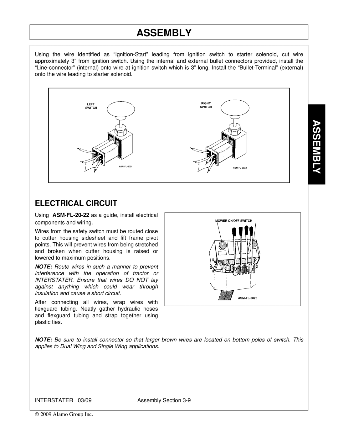
Using
Wires from the safety switch must be routed close to cutter housing sidesheet and lift frame pivot points. This will prevent wires from being stretched and broken when cutter housing is raised or lowered to maximum positions.
NOTE: Route wires in such a manner to prevent interference with the operation of tractor or INTERSTATER. Ensure that wires DO NOT lay against anything which could wear through insulation and cause a short circuit.
After connecting all wires, wrap wires with flexguard tubing. Neatly gather hydraulic hoses and flexguard tubing and strap together using plastic ties.
NOTE: Be sure to install connector so that larger brown wires are located on bottom poles of switch. This applies to Dual Wing and Single Wing applications.
INTERSTATER 03/09 | Assembly Section |
© 2009 Alamo Group Inc.