ASSEMBLY
ASSEMBLY
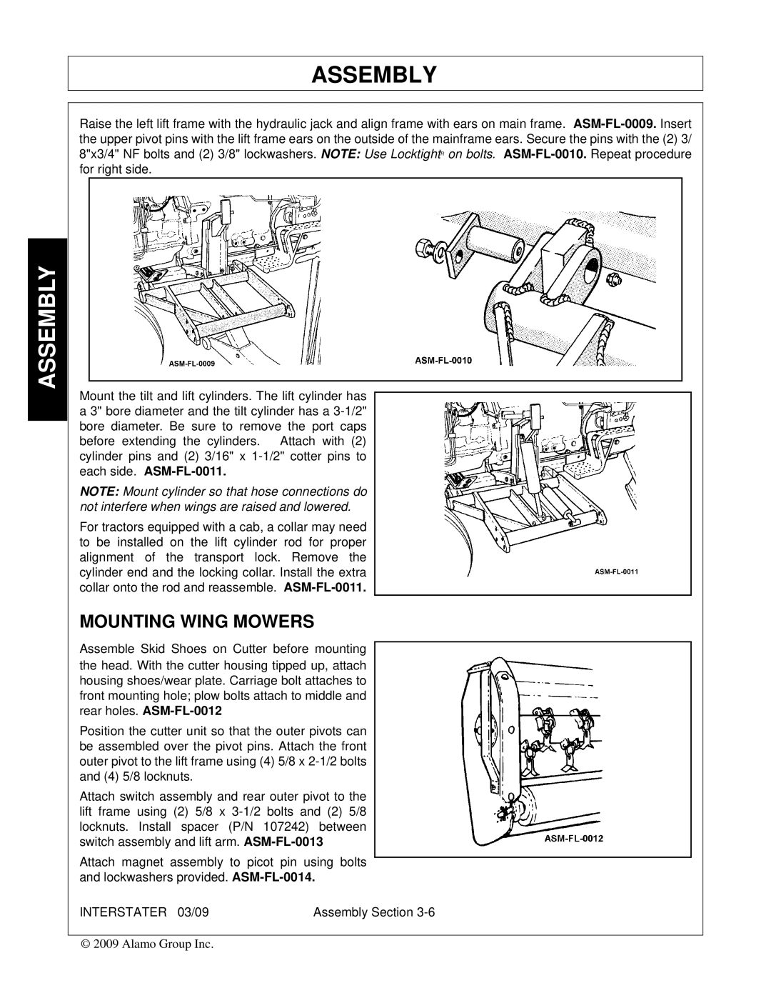
Raise the left lift frame with the hydraulic jack and align frame with ears on main frame.
Mount the tilt and lift cylinders. The lift cylinder has a 3" bore diameter and the tilt cylinder has a
NOTE: Mount cylinder so that hose connections do not interfere when wings are raised and lowered.
For tractors equipped with a cab, a collar may need to be installed on the lift cylinder rod for proper alignment of the transport lock. Remove the cylinder end and the locking collar. Install the extra collar onto the rod and reassemble.
MOUNTING WING MOWERS
Assemble Skid Shoes on Cutter before mounting the head. With the cutter housing tipped up, attach housing shoes/wear plate. Carriage bolt attaches to front mounting hole; plow bolts attach to middle and rear holes.
Position the cutter unit so that the outer pivots can be assembled over the pivot pins. Attach the front outer pivot to the lift frame using (4) 5/8 x
Attach switch assembly and rear outer pivot to the lift frame using (2) 5/8 x
Attach magnet assembly to picot pin using bolts and lockwashers provided.
INTERSTATER 03/09 | Assembly Section |
© 2009 Alamo Group Inc.