ASSEMBLY
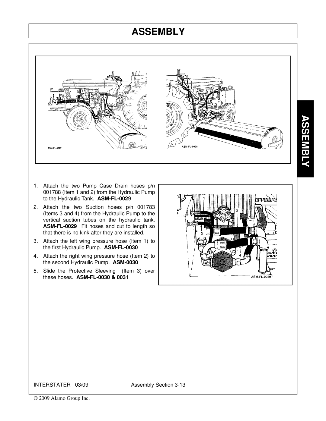
1.Attach the two Pump Case Drain hoses p/n 001788 (Item 1 and 2) from the Hydraulic Pump to the Hydraulic Tank.
2.Attach the two Suction hoses p/n 001783 (Items 3 and 4) from the Hydraulic Pump to the vertical suction tubes on the hydraulic tank.
3.Attach the left wing pressure hose (Item 1) to the first Hydraulic Pump.
4.Attach the right wing pressure hose (Item 2) to the second Hydraulic Pump.
5.Slide the Protective Sleeving (Item 3) over these hoses.
INTERSTATER 03/09 | Assembly Section |
© 2009 Alamo Group Inc.